--Materials--
(1) One computer with ZDevelop3.01 or above installed.
(2) One controller.
(3) Two 24V DC power supply (Main power & IO power)
(4) Several bus drive + motor (or stepper drive + motor).
(5) A number of controller wiring terminals.
(6) Several network cables.
(7) A number of connecting wires.
(8)
Several expansion modules of different types.
--Wiring Reference--
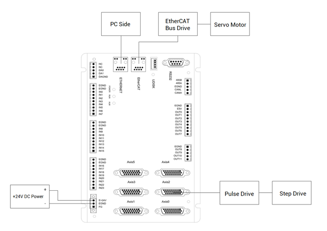
2. Expansion Module Introduction
(1) The function of expansion module
When the axis resources and IO resources of the controller itself are not enough, the expansion module can be used to expand pulse axes, digital inputs and outputs, analog inputs and outputs. But please note only the expansion module with pulse axis interface supports the expansion of the number of pulse axes.
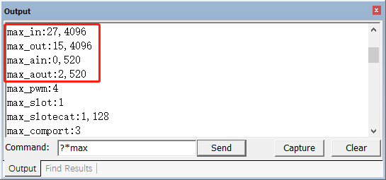
IO digital expansion: 4096 IOs can be expanded for ZMC4XX series motion controllers or above.
(the number of IOs that can be extended of motion controller can be checked through hardware manual or command "?*max")
AIO digital expansion: 520 AIOs can be expanded for ZMC4XX series motion controllers or above.
ZCAN bus axis expansion: 4 pulse axes can be extended, it is not recommended to use too many axis expansion boards, but the controller model that supports multiple pulse axes can be selected.
(2) The classification of expansion module
--connection method--
There are ZCAN bus expansion modules and EtherCAT expansion module.
--product series--
There are ZCAN expansion modules, EtherCAT expansion module and ZMIO300 expansion modules.
3. ZCAN Bus Expansion Module
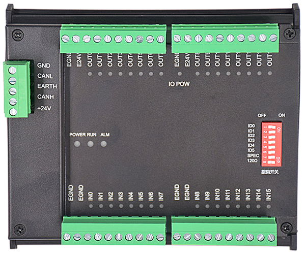
ZCAN bus expansion module contains two series, ZCAN expansion modules and ZMIO300-CAN expansion modules.
And there are many models for ZCAN expansion module, for example, ZIO1616MT, it can expand 16 inputs / 16 output (NPN). ZIO1616M-PNP expands 16 inputs / 16 outputs (PNP).
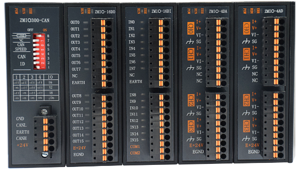
ZMIO300-CAN expansion module is vertical combined module, it can expand digital IO and analog.
(1) ZCAN expansion module
The ZCAN expansion module uses CAN bus expansion. It is recommended to use 2 expansion boards with axis numbers, but multiple expansion boards without axis numbers can be connected.
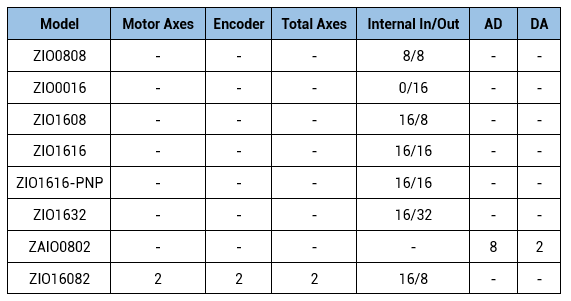
Following form shows models of ZCAN expansion module. One ZIO expansion module is with 16 inputs and 32 outputs, and one expansion module supports expanding 2 pulse axes.
The optional models of ZCAN expansion modules are as follows. One ZIO expansion module can carry 16 inputs and 32 output points, a single expansion module supports the expansion of 2 pulse axes.
The digital IO interface of the expansion module supports the NPN type by default, but the ZIO1616-PNP is the PNP type.
In addition, the extended analog input and output defaults to 0-10V type, and the resolution is 12bit.
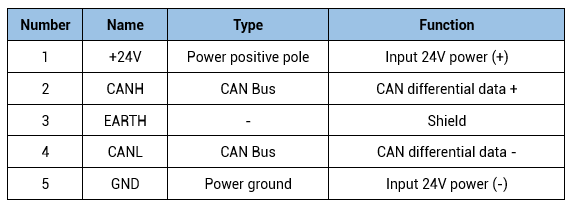
--ZCAN wiring--
When multiple CAN communication modules are connected to the CAN bus, the CANL and CANH ports of all the CAN communication modules are respectively connected together, and the eighth bit of the DIP switch of the last CAN communication module is set to ON
(indicating one 12 ohm resistor is connected between CANL and CANH), and the eighth bit DIP switches of other modules do not need to be operated.
For CAN communication, the corresponding GND must be connected, or the main power of the controller and the main power of the expansion module use the same power supply to prevent the expansion module from burning out.
ZIO series expansion modules are powered by dual power supplies, therefore, the main power supply and IO single power supply are powered by two power supplies respectively.
But the ZAIO analog expansion module is powered by a single power supply, so only the main power supply is required.
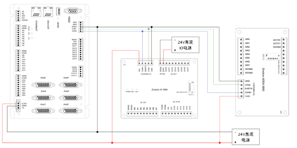
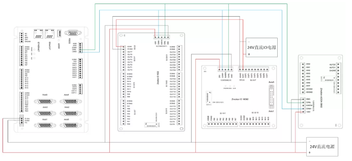
ZMC432+ZIO1608+ZAIO0802
(when in CAN expansion, please use STP (shielded twist pair), and shield is grounded.
(2) ZMIO300-CAN expansion module
From show sub modules that can be matched with ZMIO300-CAN expansion modules.
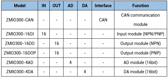
The precision of the analogs is 16 bits, and there are two input modes, NPN and PNP. What's more, the digital inputs and outputs are with the signal status indication light.
And the extended analog inputs and outputs default to 0-10V voltage type, and the resolution is 16bit.
(Note: ZMIO300-16DO/ZMIO300-16DOP in above form requires separate power supply)
--ZMIO300-CAN wiring--
The ZMIO300-CAN expansion module wiring reference is as follows, which is the same as the ZCAN expansion module wiring method.
And the eight-position DIP switch has the same definition and function as the CAN bus terminal.
For CAN communication, the corresponding GND must be connected, or the main power of the controller and the main power of the expansion module use the same power supply to prevent the expansion module from burning out.

(3) ZCAN expansion
--IO mapping expansion--
Extended resources must be mapped to controller-local resources, then they can be used.
Even though different CAN expansion modules, their methods of IO mapping and axis mapping are the same.
For IO mapping, it is set by the DIP switch on the expansion module.
For axis mapping, it is set by AXIS_ADDRESS command to map the axis number.
-DIP switch:
The ZCAN expansion module generally has an 8-bit DIP switch, dial ON to take effect, as shown in the figure:
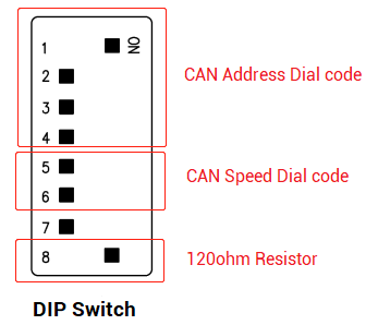
1-4: they are used for ZCAN expansion module IO address mapping, the corresponding value is 0-15.
5-6: CAN communication speed, corresponding value is 0-3, four different speeds are optional.
7: reserved.
8: 120 ohm resistor, dial ON means a 120 ohm resistor is connected between CANL and CANH.
1-4 are dialed to select CAN address, and IO number range of corresponding expansion module can be set according to CAN dialed address, so different addresses correspond to different digital IO number. Please see below form.
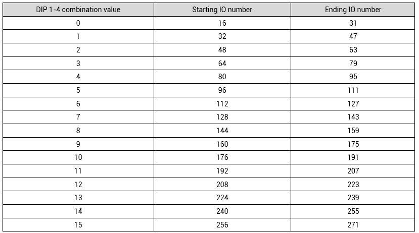
When it is dialed to OFF, the corresponding value is 0.
When it is dialed to ON, the corresponding value is 1.
Address combination value = dial 4×8+ dial 3×4+ dial 2×2+ dial 1.
And the initial IO mapping number of the digital starts from 16 and increases by multiples of 16.
In addition, the DIP switch must be dialed before the power is turned on. It is invalid to re-dial the code after the power is turned on. It needs to be powered on again to take effect.
Dial 1-4 to select the CAN address. The distribution of analog IO numbers corresponding to different addresses is as follows.
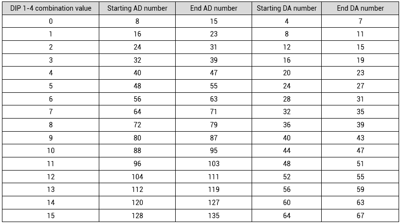
The initial IO mapping number of the analog AD starts from 8 and increases in multiples of 8.
The initial IO mapping number of the analog DA starts from 4 and increases in multiples of 4.
Dial 5-6 to select CAN communication speed, and the combination value ranges from 0 to 3.

Speed combination value=dial code 6 × 2 + dial code 5×1
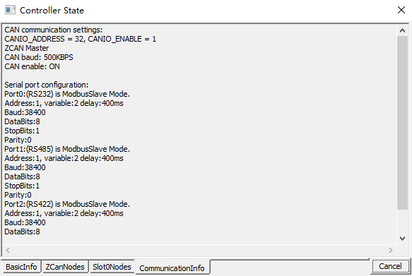
The controller side sets the CAN communication speed through the CANIO_ADDRESS command. There are also four speed parameters that can be selected. The communication speed must be consistent with the communication speed of the expansion module that corresponds to the combination value, then they can communicate with each other.
The CANIO_ADDRESS command is a system parameter, and it can set the master-slave end of CAN communication. The default value of the controller is 32, that is, CANIO_ADDRESS=32 is the master end, and the slave end is set between 0-31.
The CAN communication configuration can be viewed in the "State the Controller" window.
Notes of IO mapping and DIP switch:
The DIP switch of the expansion module is based on the largest IN and OP of the current IO points (the number of external IO interfaces + the number of IO interfaces in the pulse axis).
If the controller itself contains 28 INs and 16 OPs, then the starting address set by the first extended board should exceed the maximum value of 28. According to below rule, the dial code should be set to the combination value 1 (binary combination value 0001, from right to left, dial code 1-4, at this time dial 1 is set to ON, and the others are set to OFF). At this time, IO number on expansion module is 32-47, among them, the IOs that are vacant from 29-31 are not used.
Subsequent extended boards continue to confirm the dial settings according to the IO points in turn.
When the IO number range of the controller or expansion module is repeated, only one is valid. It is recommended to reset the dial code so that the IO numbers of the entire control system are not repeated.
--axis mapping expansion--
When the CAN bus expansion mode is used to expand the pulse axis, ZIO16082 can be selected to expand two pulse axes. These two pulse axes need to be mapped and bound with the axis No., then access.
Extended axes need to perform axis mapping operations, using the AXIS_ADDRESS command to map, and the mapping rules are as follows:
AXIS_ADDRESS(axis No.)=(32*0)+ID
'the local axis interface of the expansion module AXIS 0
AXIS_ADDRESS(axis No.)=(32*1)+ID
'the local axis interface of the expansion module AXIS 1
The ID is the combined value of the DIP bit1-4 of the expansion module. After the mapping is completed and the axis parameters such as ATYPE are set, the expansion axis can be used.
Example:
ATYPE(6)=0
'set as virtual axis
AXIS_ADDRESS(6)=1+(32*0)
'ZCAN expansion module ID 1 axis 0 is mapped to axis 6
ATYPE(6)=8
'ZCAN extended axis type, pulse direction stepping or servo
UNITS(6)=100 0 'pulse equivalent 1000
SPEED(6)=100
'speed 100uits/s
ACCEL(6)=1000
'acceleration 1000units/s^2
MOVE(100) AXIS(6) 'extended axis movement 100units
(4) ZCAN expansion module reference configuration
Configuration 1: ZIO Series
Control module configuration: 1 ZMC432+1 ZIO1632+1 ZIO16082+1 ZAIO0802
After the wiring is completed, set the DIP switch correctly, use the ZDevelop software to connect to the controller, open the "Controller" - "State the Controller" window to check the ZCAN node information, and you can see the information of all devices connected to the CAN bus.
If the CAN ID of ZIO1632 is set to 1, the extended digital input IO numbers are 32-47, there are 16 in total, and the extended digital output IO numbers are 32-63, 32 in total.
If the CAN ID of ZIO16082 is set to 3, the extended digital input IO numbers are 64-79, there are 16 in total, and the extended digital output IO numbers are 64-71, 8 in total, in addition to two pulse axes.
If the CAN ID of ZAIO0802 is set to 4, the extended analog input AD numbers are 40-47, there are 8 in total, and the extended analog output DA numbers are 20-21, 2 in total.

Configuration 2: ZMIO300 Series
Control module configuration: 1 ZMC432+1 ZMIO300-CAN communication module+4 ZMIO300-16DI input+2 ZMIO300-16DO output+2 ZMIO300-4AD+2 ZMIO300-4DA
Use the ZDevelop software to connect to the controller, open the "Controller" - "State the Controller" window to check the ZCAN node information, and you can see the information of all devices connected to the CAN bus.
If the expansion module CAN ID is set to 1, the extended digital input IO number is 32-95, there are 64 in total, the extended digital output IO number is 32-63, 32 in total. And the extended analog input AD number is 16-23, the extended analog output DA numbers are 8-15, therefore, there are 8 ADs and 8 DAs.

(5) ZCAN expansion connection status viewing
There are two ways to judge whether the connection is built or not.
--"state the controller" window--
IF CANIO_STATUS(1) =0 THEN
'judge the connection status of the CAN expansion module
PRINT "Extension module 1 is not connected"
ENDIF
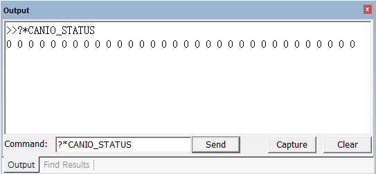
--use command "CANIO_STSTUS"--
?*CANIO_STATUS
'output the status of all CAN expansion modules
(6) ZCAN expansion module display routine
Controller module configuration: 1 ZMC432+1
ZIO1632+1
ZIO16082+1
ZAIO0802
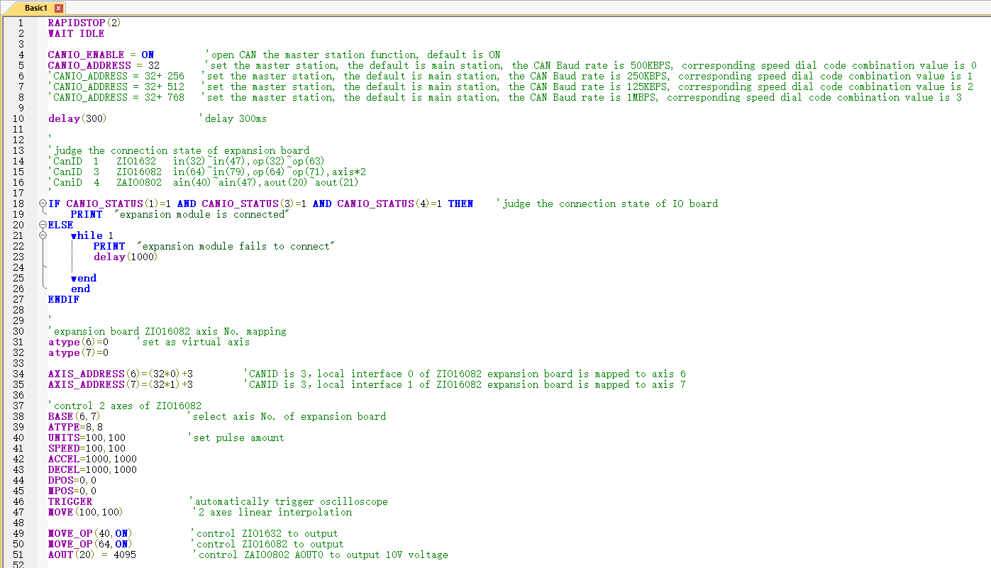
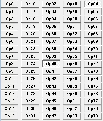
When program is executed, output states of expansion module:
That's all, thank you for your reading --
Motion Control Quick Start (7) | How to Use ZCAN Expansion Module.
For more information, please pay close attention to
"Support"
and
"Download"
, and there are other platforms about Zmotion -
Youtube
&
LinkedIn
&
Twitter
&
Tiktok
&
Facebook,
including technical information (development environment, routine code), product showing, company development, etc.
Hope to meet you, talk with you and be friends with you.
Welcome!
This article is edited by ZMOTION, here, share with you, let's learn together.
ZMOTION: DO THE BEST TO USE MOTION CONTROL.
Note: Copyright belongs to Zmotion Technology, if there is reproduction, please indicate article source. Thank you.
Zmotion Technology
focuses on development of motion control technology and general motion control products, it is a national high and new technology enterprise. Due to its concentration and hard work in motion control technology, ZMOTION already become one of the fastest growing industrial motion control companies in China, and is also the rare company who has managed core technologies of motion control and real time industrial control software completely. Here, Zmotion provides motion controller, motion control card, vision motion controller, expansion module and HMI. In addition, there is one program software developed by Zmotion -- ZDevelop. It is a good choice for you to program and compile. And program through upper computer, there is PC manual.
Zmotion Technology
provides motion control card, motion controller, vision motion controller, expansion module and HMI. (
more keywords
for Zmotion: EtherCAT motion control card, EtherCAT motion controller, motion control system, vision controller, motion control PLC, robot controller, vision positioning...)
Have a good day, best wishes, see you next time.


