
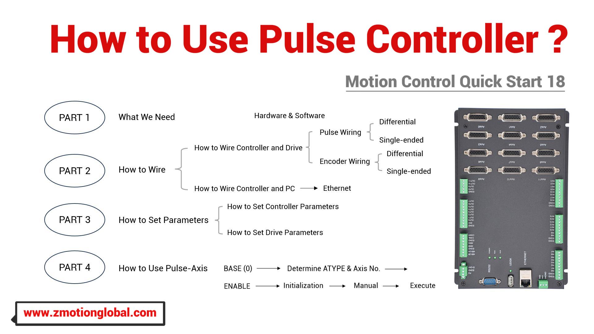
1. What We Need?
2. How to Wire?
(1) How to Wire Controller Pulse and Drive
(2) How to Connect Controller to Encoder
(3) How to Connect Drive to Motor / Encoder
(4) How to Connect Controller to PC
3. How to Set Controller Parameters
(1) Axis Type Configuration
(2) Pulse-Axis No. Configuration
4. How to Set Drive Parameters
(1) Parameters Modification
(2) Drive Alaram Checking
(1) Enable Pulse-Axis
(2) Check Problems by "Manual"
(3) Download Motion Control Program
1. What We Need
(1) Hardware
A. one ZMC412 controller that supports 12 pulse axes.
B. one set of Panasonic servo drive + motor that is with pulse interface.
C. one PC.
D. one cable with shielded.
E. one 24V DC power supply
F. one pulse-axis connecting line
G. wiring terminals and connecting lines as needed.
(2) Software
A. Motion Controller Programming Software:
ZDevelop latest controller programming software (download from here or contact us, no need installing, run it directly after compressed)
B. Panasonic Drive Host-Computer Debugging Software
PANATERM (download from Panasonic website)

2. How to Wire
Here, we mainly talk about ZMC412 12-axis pulse motion controller, so let's know it briefly.
ZMC412 is one high-performance motion controller, which means it can achieve rich motion control functions, such as, linear, circular, helical interpolation, electronic cam, electronic gear, synchronous follow, hardware comparison output, hardware timer, precision output in motion, pulse closed-loop, pitch compensation, multi-file & multi-task programming, etc. In addition, real-time motion control can be realized through optimized network communication protocol.
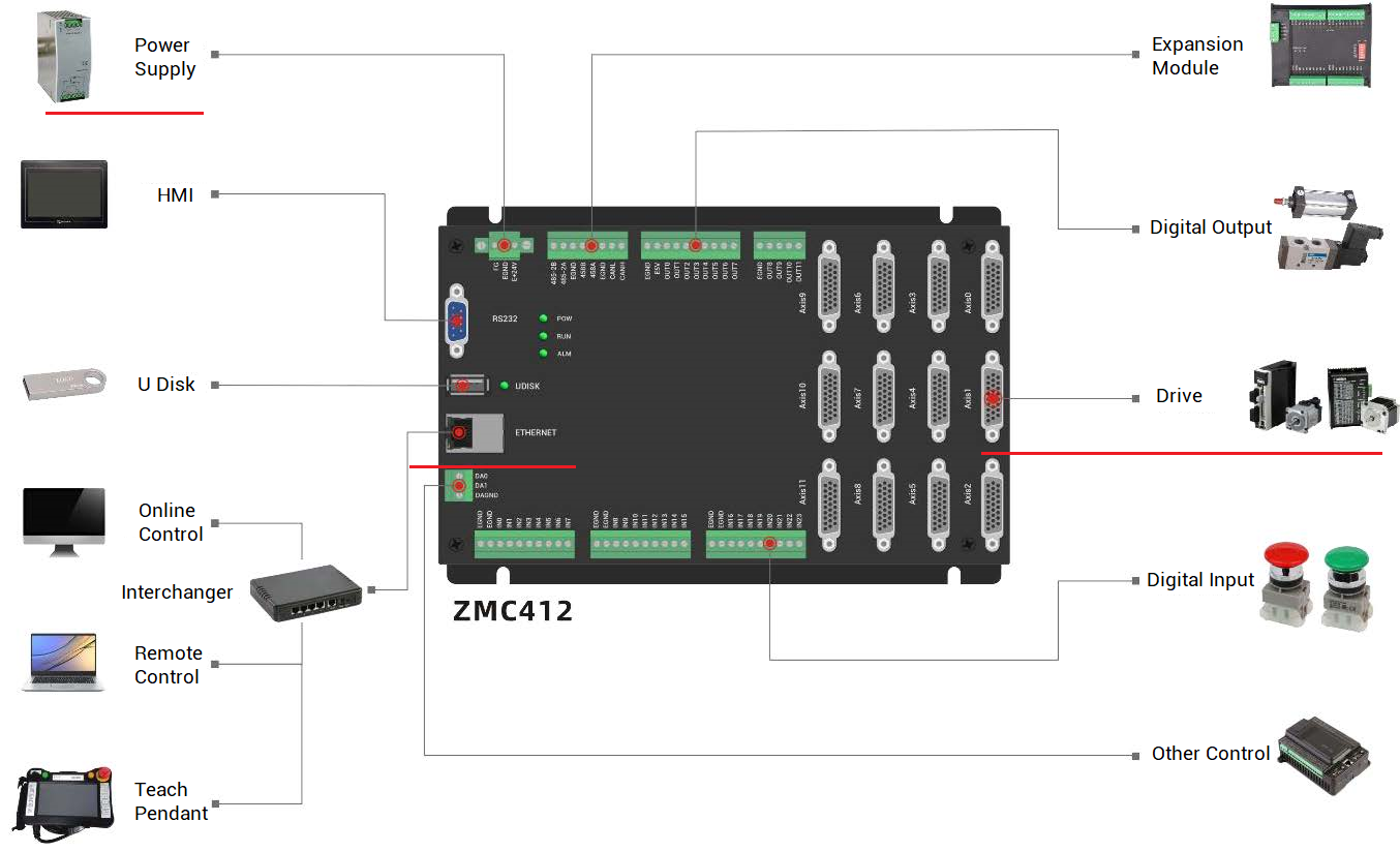
It can be seen that it has Ethernet, USB, CAN, 232, 485 communication interfaces. and there are 12 pulse axes, if we need more pulse axes or IO resources, expansion modules can be connected through CAN protocol, please note one 120ohm resistor on both sides of CAN bus.
Next, see three main interfaces for wiring.
--Main Power Supply--
connect E+24V of controller main power supply to positive pole of 24V DC power supply, and connect EGND to negative pole of 24V DC power supply.
--EtherNET--
use one cable to connect controller EtherNET to PC Ethernet port.
--Pulse--
connect pulse to drive
example: use the specialized cable with shield to connect controller to Panasonic A6, one is to pulse axis, another is to drive X4 interface. If there is no pulse axis in drive that can be connected directly, please refer to below knowledge.
(1) How to Wire Controller Pulse and Drive
It only needs to use one twisted cable with shield to link controller pulse axis with drive terminal.
Before that, please check the number of pulse axes from corresponding controller hardware manual, or ?*max, or controller state in ZDevelop.
Generally, controller pulse-axis interface is 26 PIN, which includes pulse wiring terminal and encoder terminal.
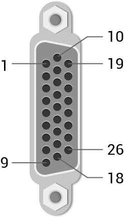
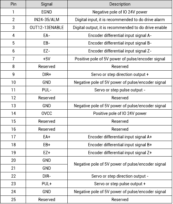
In above form, it can be known there are general outputs in pulse-axis. Actually these outputs are behind controller outputs. That is, ZMC412 controller has 12 OUT, and they are 0-11, then it still has 12 OUT in 12 pulse axes (AXIS 0-11), so these OUT should be 12-23 as the enable signal for each axis. Therefore, PIN3 means general OUT in AXIS for enabling motor. When OUT12 is ON, then drive connected on AXIS 0 is also enabled, when OUT13 is ON, drive on AXIS 1 is enabled, and so on.
For wiring controller pulse and drive pulse, there are two methods, differential connection and single-ended connection.
Let's see one by one.
A. Differential Method
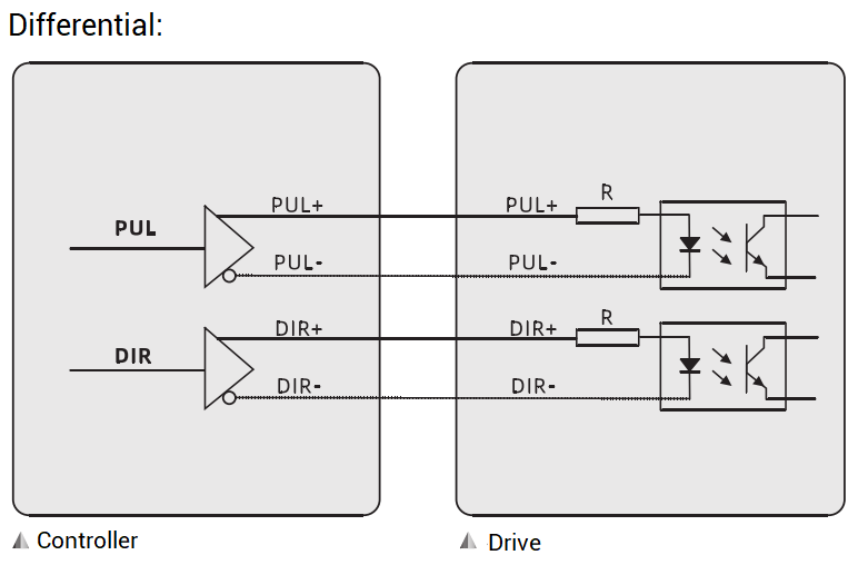
Connect PUL+, PUL-, DIR+, DIR- correspondingly.
B. Single-Ended Method
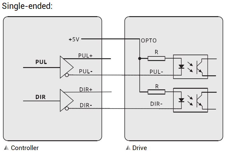
Single-ended connection is common anode wiring, specifically, it connects PUL- and DIR- of controller and drive, then for PUL+ and DIR+ terminals, in controller side, they are not used, in drive side, they are connected to controller 5V power supply.
Differential wiring is to judge voltage difference between 2 signal cables. For differential input, two cables are influenced at the same time when there is interference, but no big change on voltage difference. However, for single-ended wiring, when one cable's voltage changes, then their voltage difference becomes bigger also because power voltage is still.
That is, the anti-interference ability of differential method is better.
See more references in detail for differential connection.
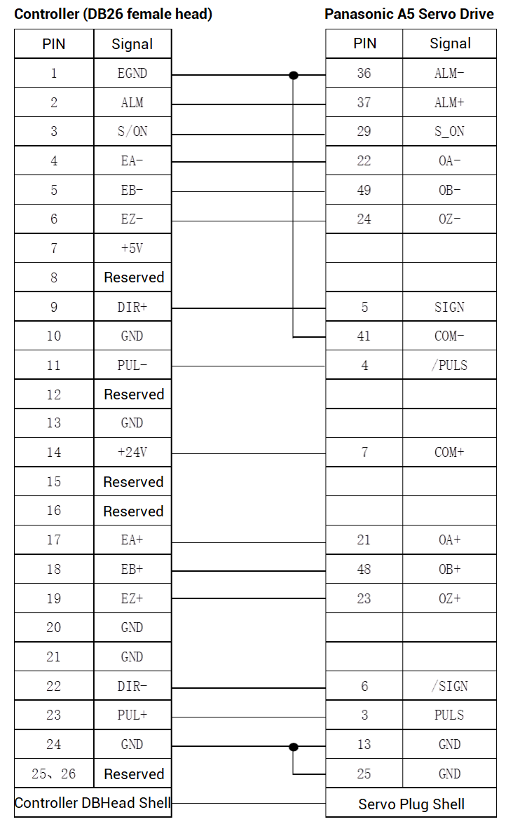
low-speed differential connection
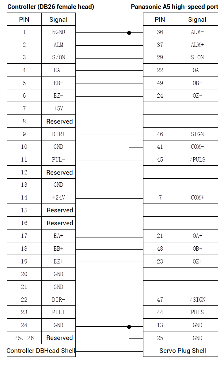
high-speed differential connection
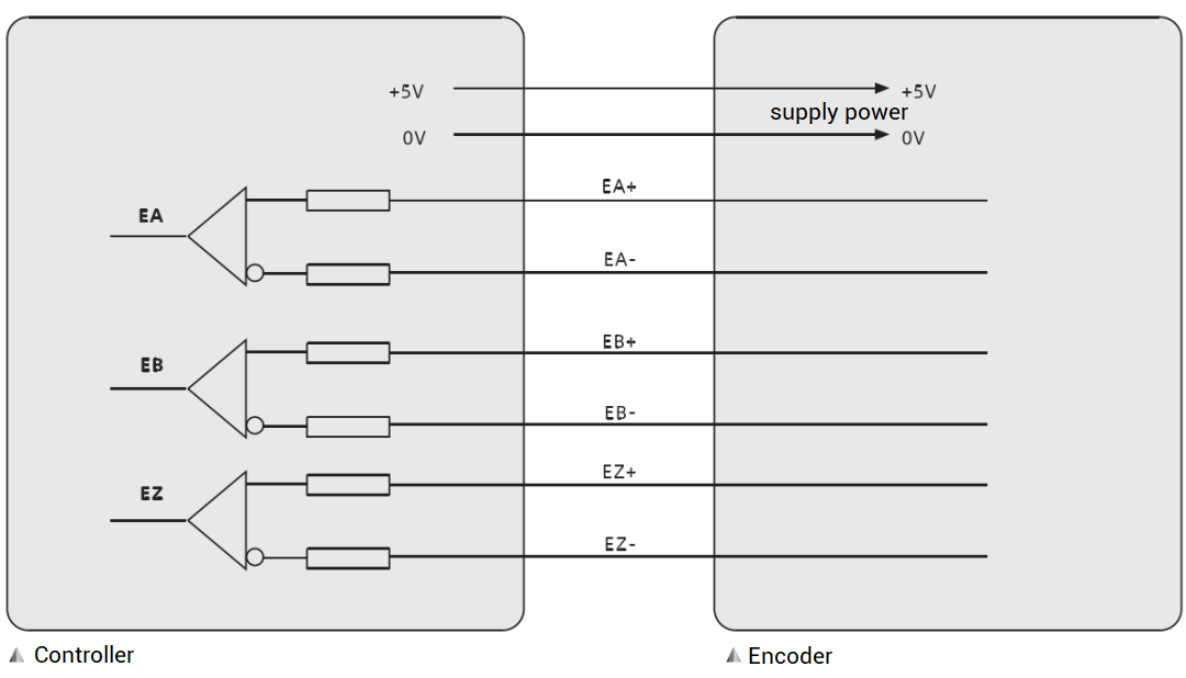
(2) How to Connect Controller to Encoder
For Zmotion motion controller, pulse axis interface only can connect to 5V encoder, but some controllers can connect to 24V encoder on IO terminal, please check from hardware manual (while using 24V encoder, ground cable is EGND).
5V encoder also has differential and single-ended connection ways.
Differential wiring: same as ordinary encoder, connect EA+ to A+, connect EA- to A-, connect correspondingly.
Single-ended wiring: connect encoder A to controller EA+, connect encoder B to controller EB+, controller's EA- and EB- are spare.
Whatever which one, please remember to make controller and encoder ground. It is inside GND in pulse axis interface (for 26 pin, they are 10, 13, 24), not IO ground (EGND).
(3) How to Connect Drive to Motor / Encoder
Please refer to "Panasonic A6 Drive Manual", connect drive to 220V city power.
(4) How to Connect Controller to PC
Also, there are two ways to connect them, serial port, or net port. Next, we make the description through Ethernet.
--Connection Steps--
A. Hardware wiring
Connect controller to PC through one good quality cable, power on controller power.
B. Software wiring
When controller powered on, open our Zmotion free programming software ZDevelop.
a. click "controller" -- "connect" to open "connect to controller" window.
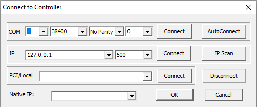
"connect to controller" window
b. check local IP in this window "IP selection".
Drop down the IP, all valid controller IP addresses in current LAN will be shown, then we could select one, please note their front three network segment must be consistent. Generally, controller factory IP is 192.168.0.11. When controller POWER and RUN led are ON, this controller IP address can be found. If no needed IP, please use "IP Scan", and drop down to select again.
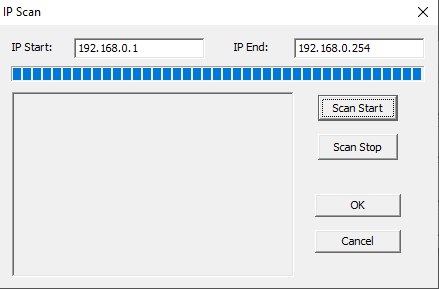
c. after confirming IP, click "connect". Now, connected.

If they don't in same segment, it needs to modify controller or PC IP to make them be the same.
--How to Modify Controller IP--
A. connect to controller through "serial port" to get the address.
B. modify IP in ZDevelop.
Method 1:
click "controller" -- "modify IP address" to modify it directly.

Method 2:
send "IP_ADDRESS" command.

Note: the new IP is valid all the time.
--How to Modify PC IP (WIN10)--
A. click "control panel" -- "Network and Sharing Center" -- "Ethernet"
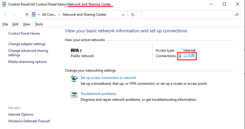
B. in "Ethernet Status" window, click "Properties", find "Internet protocol version 4 (TCP/IPV4) and open it, then check "Use the following IP address". At this time, we could modify it. Please remember to click "OK".
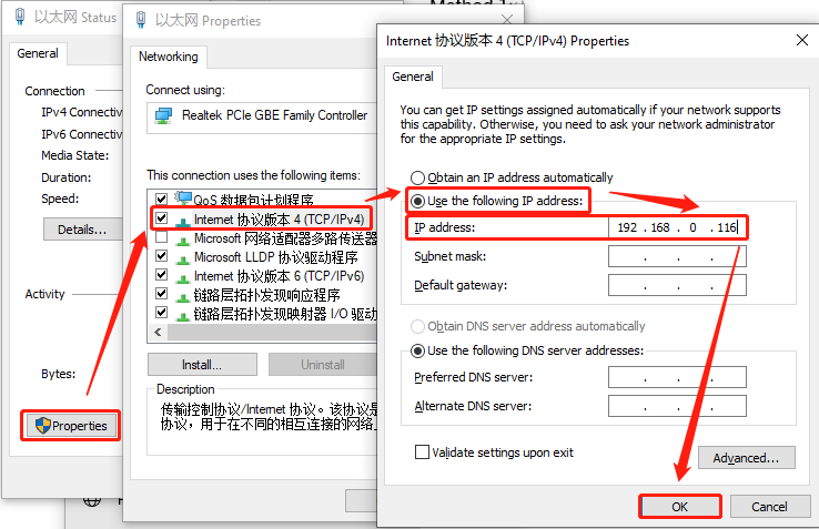
C. connect again in "connect to controller" window.
3. How to Set Controller Parameters
(1) Axis Type Configuration
It only needs to set "ATYPE" value well in initialization. And it must be consistent as actual axis.
For pulse-axis, please set it as 1/7.
For EtherCAT axis, please set it as 65/66/67.
For RTEX axis, please set it as 50/51/52.
For more details, please refer to below form.
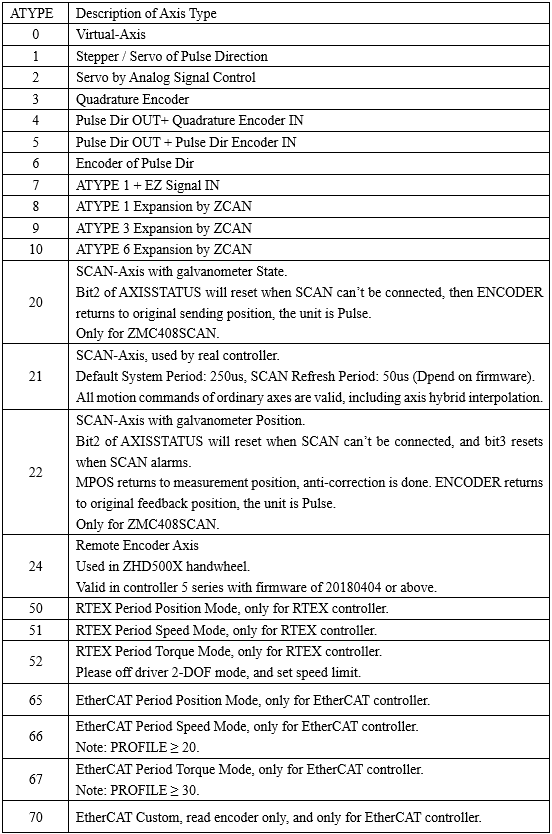
As it is mentioned, set it as 1/7 for pulse axis, actually 4 is also OK. But:
ATYPE = 1/7: no encoder, MPOS (encoder feedback position) is false, so MPOS is same as DPOS (axis demand position).
ATYPE = 4: encoder can be connected, and MPOS represents real feedback.
For ZMC4XX controller, when it is set as servo / stepper pulse output mode through INVERT_STEP, dual-pulse, pulse + direction, and quadrate pulse mode can be selected.
?INVERT_STEP(n) / ?INVERT_STEP AXIS(n) 'n is the axis No.
?*INVERT_STEP '?* to check all axis parameters
(2) Pulse-Axis No. Configuration
When pulse-axis is used, axis No. on drive is determined by controller pulse axis No., which means no need axis mapping. For example, if controller AXIS 0 is connected, motor axis No. of drive is 0. And if we want to know which axis No. gets the encoder feedback, please check "controller" -- "state the controller".
In "controller status" window, we also could know each axis' supported axis type. Specifically, in "Axis features list".
"Step Encoder" means it supports pulse output "Step" and encoder measurement "Encoder" (when ATYPE = 4).
"Encoder" means measurement axis No. And usually this kind of ATYPE is 3 (quadrate encoder) by default, also can be 6 (pulse directional encoder).
For example , ZMC432.
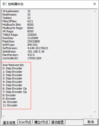
It has 6 pulse-axis interfaces, then
Pulse output axis No. are 0, 1, 2, 3, 4, 5.
Encoder feedback axis No. are 6, 7, 8, 9, 10, 11
In first pulse-axis interface, there are 2 axis No., 0 (output device: motor) and 6 (feedback device: encoder).
In second pulse-axis interface, there are axis 1 and axis 7.
In third pulse-axis interface, there are axis 2 and axis 8.
......
Different controller models are with different.
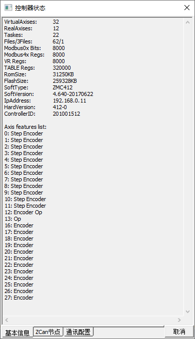
ZMC412 : axis 0 - axis 11 are pulse axes, axis 16 - axis 27 can be configured as encoder (then, map them into encoder axis 0 - 11).
4. How to Set Drive Parameters
For drive parameters, please use drive software.
(1) Parameters Modification
A. Do connection
Connect to drive through USB or WLAN.
Here, USB connection method is mainly introduced: connect PC and drive X1 through USB cable.
B. Power on drive
C. Open drive software "PANATERM".
When "Select communication with drive" window, please select USB one, then drive information are obtained and shown in window, after clicking "OK", it is time to set drive parameters.
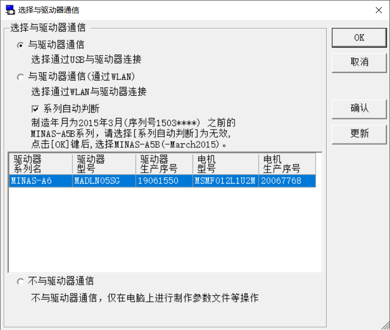
In this setting, drive IO must be set correctly. Otherwise, it will lead position limit alarm. If position limit level reverse is needed, please go to "Parameter" window.
D. Open "Parameter" window
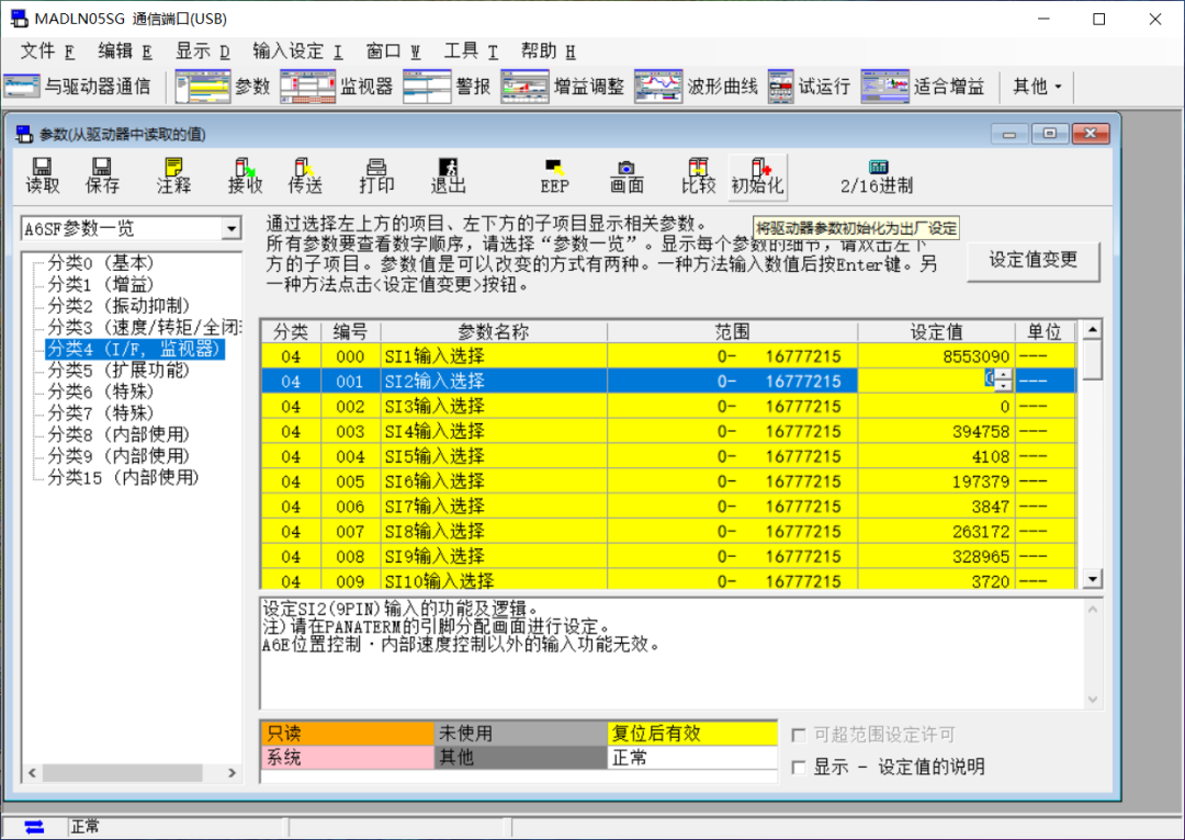
In left, choose the parameter and open it, IO is type 4. Then, write the new value in "set value" and save it. Next, write the parameter into drive.
"Initialize" button is used to make set values of IO resume default configuration.
E. Write new parameter into drive.
After setting value in "Parameter", click "transfer" to pass modified parameters into drive, then click "EEP" to write parameters into drive EEPROM.
F. Power on drive again
Now, it can be seen modified parameters take effect.
(2) Drive Alaram Checking
Method 1: Check in ZDevelop
In ZDevelop, we could view drive alarm information printed in "Command & Output" window, or view AXISSTATUS value.
Method 2: Check in Drive Hardware
See whether LED on drive has an error, if there is not correct, corresponding error code will shown, then please check and clear it according to drive manual.
Method 3: Check in Drive Software
In PANATERM "alarm" window, current drive alarm information will be shown, or check through "history alarms".
ABOUT ZMOTION
That's all, thank you for your reading -- Motion Control Quick Start 18 | How to Use Pulse Motion Controller