
Laser Galvanometer Control of Zmotion is mainly achieved by SCAN motion controller, like, ZMC408SCAN, ZMC420SCAN. Then, use ZBasic to develop the project and debug in ZDevelop programming software.
Galvanometer motion control includes laser control and motion control , and only these two controls matched, it can achieve effective laser applications, such as, laser marking, laser cutting, laser welding, etc., and in Zmotion, ZMC420SCAN controller can meet these requirements well.
Video Description 1: Laser Galvanometer Control By Motion Controller -- Knowledge Introduction
Video Description 2: Laser Galvanometer Control By Motion Controller -- Laser Information & Routine Display.
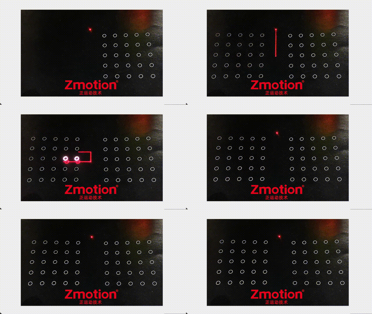
Above shows laser galvanometer control actual effects.
Now, let's learn ZMC420SCAN laser galvanometer motion controller and its application development and achievement.
--Hardware Material--
one ZMC420SCAN controller that is with Scan-axis interface.
one laser galvanometer device that includes one laser generator and two scan-axis.
one PC.
two net cables that are with shield layer.
one 24V DC power supply.
one set of servo driver + motor.
several wiring terminals and connection cables.
--Software Material--
ZDevelop V3.10 controller programming software.
It can be downloaded from Zmotion official website, and it can run application program directly after compressing it, no need to install, or contact us directly.
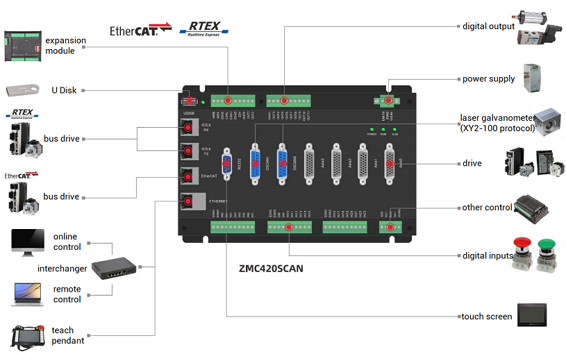
(1) main power supply: connect E+24V terminal on main power supply wiring terminal to 24V DC power positive pole, and connect EGND terminal to 24V DC power negative pole.
(2) Ethernet wiring: use one net cable to connect controller EtherNET port with PC ethernet.
(3) laser galvanometer head (SCAN-HEAD) and controller wiring: connect two scan axes in laser scan head to scan axis interface AXIS 4 of controller, at this time, scan axes are axis 4 and axis 5, then connect each interface of laser generator to controller OUT according to requirements.
(4)if the workpiece that is to be mark needs actions, connect the axis that controls workpiece motion to controller pulse axis interface or bus axis interface.
(1) Controller
ZMC420SCAN is a kind of 20 axes bus type controller, which includes two scan-axis interfaces. It not only supports pulse axis, but also supports ECAT/RTEX bus axis. It can achieve many functions through max 20 axes motion control, such as, linear interpolation, any circular interpolation, space arc, helical interpolation, electronic cam, electronic gear, synchronous follow, virtual axis, etc. In addition, real-time motion control can be realized through optimized network communication protocol.
ZMC420SCAN bus controller supports hybrid interpolation among pulse axis, bus axis and galvanometer axis (scan-axis).
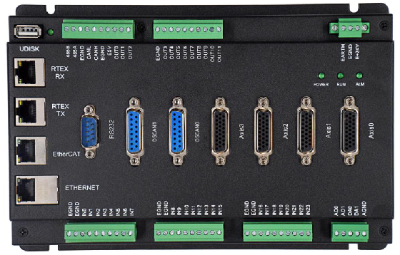
Please refer to below ZMC420SCAN, there are 24 inputs, 12 outputs, 2 ADs and 2 DAs, encoder axis can be configured as handwheel input, and all outputs support high-speed PWM control.
(2) Laser Galvanometer (Laser Scan)
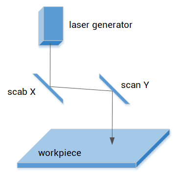
Laser galvanometer is a special motion element that is specified for laser processing area. The main elements in laser scan head are laser generator, two motors and two scan lens. It controls scan lens X and Y through two motors, then form XY platform motion, and these two motors are controlled by scan-axis interface on ZMC420SCAN controller.
Laser galvanometer is different from general motor, namely, laser galvanometer has extremely small inertia, and load is extremely small when in motion, it only needs to drive reflective lens, system respond is very quick.
(1) Galvanometer-axis Control
ZMC420SCAN supports XY2-100 scan protocol, and joint interpolation motion of motion control and galvanometer is valid.
And host computer is connected through ethernet and controller.
--for galvanometer axis motion, it is controlled through XY2-100 scan protocol
--for servo axis motion, it is controlled through bus protocol or pulse mode.
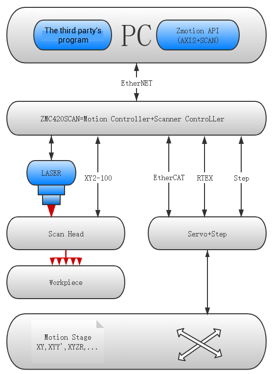
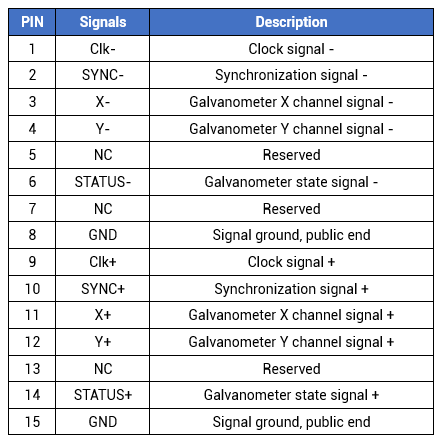
According to above image, use ZMC420SCAN controller scan axis interface to laser galvanometer head, each scan axis interface contains two galvanometer channel signals to control offsets of scan lens X, Y respectively, then the position of workpiece where is marked by laser can be controlled.
Except ZDevelop software, upper computer software can be used to develop laser galvanometer program. There is one uniform set of API function.

--valid development languages: C, C++, C#, LabView, Python, Delphi.
--valid platforms: VC6.0, VB6.0, Qt, .Net
--valid operation systems: Windows, Linux, WinCE, iMac.
Actually, laser motions are achieved through motion commands.
For example, laser marking motion control.
When OUT that supports PWM function is connected to laser generator of laser galvanometer, then use command to control laser frequency, laser output and laser then achieve laser marking.
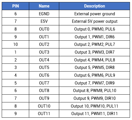
ZMC420SCAN external general output OUT0-11 all have PWM output function, and PWM output is controlled by normal output function. Only when output status is ON, PWM can output actually, in this way, laser energy can be controlled.
As mentioned above, motion commands achieves laser galvanometer control. There are two major relative commands, PWM_DUTY and PWM_FREQ.
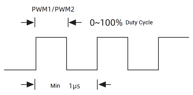
--PWM_DUTY is used to set laser duty cycle , 1 means laser is in ON status all the time when in processing motion, 0 means laser OFF.
--PWM_FREQ is used to set laser frequency.
Except these two commands, there is one MOVE_OP instruction. When laser parameters are set well, use MOVE_OP to operate whether outputs laser.
(2) Laser Control Command
PWM_DUTY -- PWM Duty Cycle
The duty cycle of PWM is used to control the laser energy output. PWM can only be turned off by setting the duty cycle to 0, but not by setting the PWM frequency to 0. And the PWM frequency must be adjusted before the PWM switch.
The duty cycle refers to the ratio of the active level to the entire cycle. In one cycle, the active level is output first, and then the inactive level is output.
Syntax 1: PWM_DUTY(No., duty cycle)
Syntax 2: PWM_DUTY (No.) = duty cycle
When selecting PWM output No., be sure to select the OUT port that supports the PWM function. The duty cycle range is 0-1, when it is set to 0, the PWM is off, when it is set to 1, the PWM is normally on.
PWM_FREQ -- PWM Frequency
PWM frequency setting or reading, the higher the frequency, the more frequent the level jump.
Syntax 1: PWM_FREQ(No., frequency)
Syntax 2: PWM_FREQ(No.)=Frequency
The PWM output frequency is limited, the hardware PWM is up to 1MHz, and the software PWM is up to 2KHz.
MOVE_PWM -- Buffer PWM
Operate PWM in BASE axis motion buffer, and it does not do any movement when the command buffer is executed, only operates PWM.
PWM can only be turned off by setting the duty cycle to 0, not by setting the PWM frequency to 0.
Grammar:
MOVE_PWM(pwmindex, duty[, freq])
pwmindex: pwm No.
Duty: duty cycle, which refers to the ratio of the active level to the entire cycle, the range is 0-1, when it is set to 0, the pwm is turned off, in a cycle, the active level is output first, and then the invalid level is output
freq: frequency, the default is 1KHz, the hardware maximum is 1MHz, the software maximum is 2KHz.
Example: output and modify PWM in motion buffer
BASE(0)
ATYPE=1
UNITS=100
SPEED=100 'initial speed
ACCEL=1000
DECEL=1000
DPOS=0
MOVE_PWM(0, 0, 1000) 'turn off PWM
MOVE(10)
MOVE_PWM(0, 0.111, 2000) 'when axis 0 runs to 10, operate PWM0 to output.
MOVE_DELAY(100)
MOVE_PWM(0, 0.555, 3000) 'delay 100ms, modify PWM0 output
MOVE(20)
MOVE_PWM(0, 0, 1000) 'turn off PWM
END
(3) Scan Axis Interface
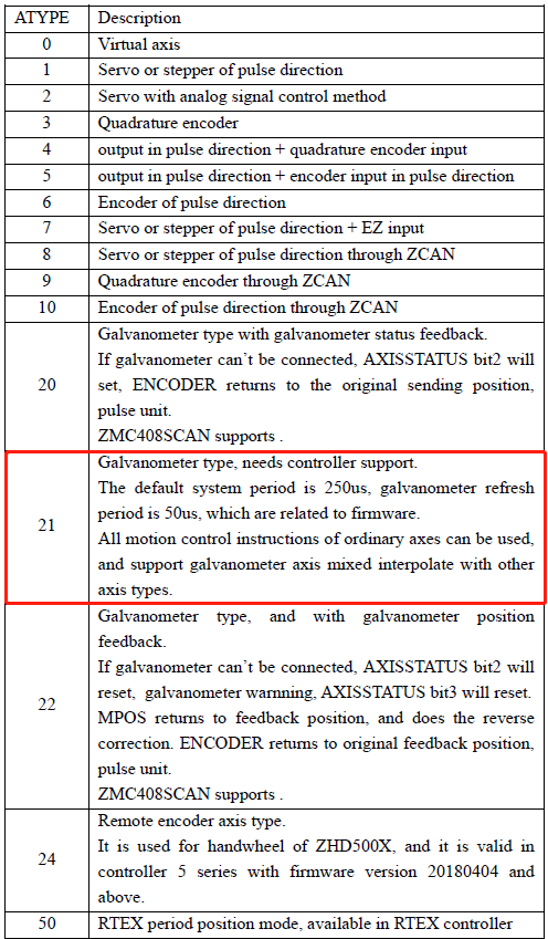
ZMC420SCAN is with 2 scan-axis interfaces, and local axis 4/5 can be configured as the first galvanometer (scan) through ATYPE=21, and local axis 6/7 can be configured as the second galvanometer (scan) through ATYPE=21. The axis No. can be modified by AXIS_ADDRESS axis mapping instruction.
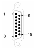
It should set mode 21 for ATYPE to set axis as galvanometer axis. And system period and refresh period of scan-axis are faster than ordinary axes.
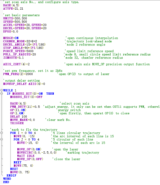
ZMC420SCAN OUT0-7 have the function of precision output , and each precision output is independent mutually, the same one period can open multiple precision outputs at the same time. Corresponding command is AXIS_ZSET, which is used to set whether each MOVE_OP uses precision output. Sometimes, if precision output delay is required, MOVEOP_DELAY command can achieve it, then control laser PSO.
Next, let' see AXIS_ZSET in detail.
AXIS_ZSET -- open precision output
Turn on MOVE_OP precision output function for axis, one command only opens one axis, which is used for master axis. Please note it needs the OP port that supports precision output function.
Parameters:
bit0: 1 - VP_SPEED uses interpolation speed by default, 0 - VP_SPEED uses single-axis speed
bit1: 1 - use MOVE_OP precise output function, 0 - MOVE_OP is normal output
bit4: 1 - for the axis with encoder function, use the MOVE_OP precise method of the encoder position. When interpolating multiple encoder axes, enable the precise output setting for the main axis of BASE motion.
Readable: VALUE=AXIS_ZSET
Writable: AXIS_ZSET=VALUE
Even though the SYSTEM_ZSET command can also be used to enable precise output, and the parameter settings are the same as the AXIS_ZSET command, when SYSTEM_ZSET is modified, the AXIS_ZSET of the current BASE axis will be modified to be compatible with the old program. Therefore, it is generally recommended to use the AXIS_ZSET command.
And once SYSTEM_ZSET is turned on, all the outputs that support the precision output function will become precision mode. Generally, it is not necessary to turn them all on during use. When the precision output function of some controller models is not independent, only one precision output port can be operated in one controller cycle, and it is not better to use this command for the new version of the firmware, directly use the AXIS_ZSET command to enable the precise output of the main axis.
Precise output enable method:
AXIS_ZSET(0)=19 'use the MOVE_OP precise method of MPOS at the encoder position of the main axis 0, and an encoder is required
AXIS_ZSET(0)=2 'without encoder, use MOVE_OP precision method of target position DPOS
MOVE_OP(0,1) 'precision takes effect, select output channel 0
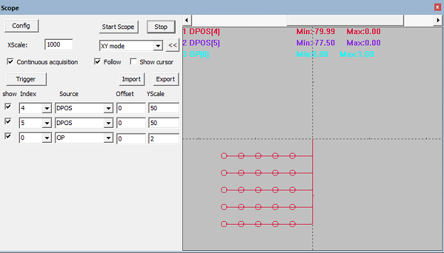
Here, use laser to process 25 arcs. After the axis moves to the specified position, open the OP port to control the laser output. And after the marking track is completed, close the OP port. At this time, the laser cannot output. Open OP port marking again after the next position to be marked.
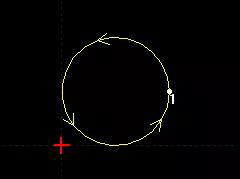
The arc marking direction is as shown in the figure below: the trajectory can be realized by one circular interpolation command or multiple linear interpolation commands to walk a small line segment, where the trajectory is a counterclockwise full circle with a radius of 2.5.
ABOUT ZMOTION
That's all, thank you for your reading -- Laser Galvanometer Motion Controller
For more information, please pay close attention to "Support" and "Download" , and there are other platforms about Zmotion - Youtube & LinkedIn & Twitter & Tiktok & Facebook, including technical information (development environment, routine code), product showing, company development, etc.
Hope to meet you, talk with you and be friends with you. Welcome!
This article is edited by ZMOTION, here, share with you, let's learn together.
ZMOTION: DO THE BEST TO USE MOTION CONTROL.
Note: Copyright belongs to Zmotion Technology, if there is reproduction, please indicate article source. Thank you.
Zmotion Technology focuses on development of motion control technology and general motion control products, it is a national high and new technology enterprise. Due to its concentration and hard work in motion control technology, ZMOTION already become one of the fastest growing industrial motion control companies in China, and is also the rare company who has managed core technologies of motion control and real time industrial control software completely. Here, Zmotion provides motion controller, motion control card, vision motion controller, expansion module and HMI