


Have a nice day !
Today, ZMotion shares how to rapidly learn ZMC motion controller application in SCARA robots.
Let's begin.
1 computer
1 ZMC406 controller
1 DC 24V power supply
1 SCARA robot arm
Several controller wiring terminals
Several net cables
Several connection lines
According to your specific requirements, IO equipment, expansion module and others can be used.
SCARA (Selective Compliance Assembly Robot Arm) is a special type of industrial robot with cylindrical coordinates. SCARA robots can be manufactured in various sizes, generally, the most common working radius is between 100 mm and 1000 mm, and the net deadweight of this kind of SCARA robots is between 1 kg and 200 kg. In addition, the SCARA system has compliance in the directions "x and y", but has good rigidity in the direction of axis Z, including the characteristics of a two-bar structure connected in series, which is suitable for handling parts and assembly work. Therefore, the SCARA system can be widely used in the assembly of printed circuit boards, electronic components, and integrated circuit boards, plastics, automobiles, electronic products, pharmaceuticals, food and other industrial areas.
Now, we know what is SCARA, the features and applications. Then, let's see how ZMC motion controllers are ?
ZMC motion controllers are developed by ZMotion. There are many models, which means corresponding axes, such as, 6-axis, 12-axis, 20-axis, 30-axis, 32-axis, 60-axis, 64-axis, etc. And there are many valid functions for them, linear interpolation, arbitrary circular interpolation, space circular and helical interpolation, electronic cam, electronic gear, synchronous follow, virtual axis setting, robot instructions, etc.
The most, this article uses the ZMC motion controller to introduce the application of the robot instruction "CONNFRAME" to the SCARA robot.
ZMC motion controller uses simple and easy-to-understand BASIC program to re-develop the robot program. It supports multi-file multi-task operation, and supports customized instructions, In addition, there is a powerful ZDevelop development environment, which supports PC simulation operation and online tracking and debugging. And complex motion control can be easier and clearer together with VC operating habit. Except ZDevelop, common PC upper computer softwares also can be used, such as VC, VB, VS, C++, C#, etc. According to different development environments, download the PC function library from ZMotion official website to find the corresponding dll Link library and related files, then use ZAux_Direct_Connframe and ZAux_Direct_Connreframe commands to establish manipulator connection in programming.
The CONNFRAME instruction can achieve SCARA robot motion, easy and convenient programming. And the motion is smooth and precise for motor motion. Customers have unanimously recognized the performance and quality of ZMC products, and ZMotion Technology will also customize special instructions and controller models according to different requirements of different customers.
(1) SCARA Robot Arm
SCARA robots support 2-4 axes, they are large joint axis + small joint axis [+Z axis] [+end rotation axis]
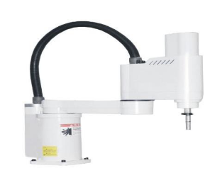
This system is applied in standard SCARA robot arm, which means there are 2 joint-axes X and Y, one up-down axis Z and one terminal rotation axis R. Then, motion control should support robot arm function, downloading edited program into controller through offline method (or using PC to watch / send instruction real-time). For motion trajectory, HMI teaching method can be used to edit satisfied trajectory.
(2) ZMC Motion Controller
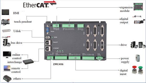
As mentioned before, the controller should be with robot function. Here, ZMC406 bus controller is a good choice. It is a 6-axis PC based motion controller developed by ZMotion (extend axes through expansion module, 32 axes at most), and it has 6 pulse-axis interfaces.
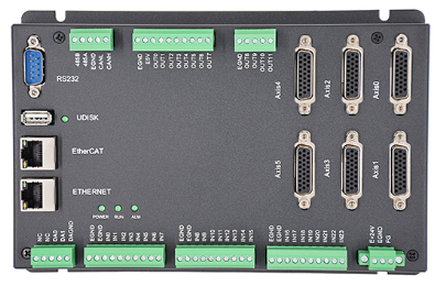
ZMC406 supports RS232, RS485, EtherNet, U disk, CAN and EtherCAT communication interfaces. The fastest EtherCAT refresh cycle is 500us. And the output current can reach 300mA, which can drive some valves directly. Each output pulse frequency can reach 10MHZ. In addition, real-time motion control can be achieved through optimized network communication protocol. Also, it supports encoder measurements, which can be configured as handwheel input mode. One computer support 256 ZMC controllers link together at most.
ZMC406 Motion Controller VS PCI Motion Control Card
Advantages:
1. no need of slots, better stability.
2. MINI compute or ARM industrial PC can be used to reduce whole cost.
3. controller can be used as wiring board to save space.
4. program can run parallelly on controller, it only needs simple interaction with PC. Then, complexity of PC software can be reduced.
ZMC controllers are debugged through ZDevelop development environment. It is really convenient to program, compile and debug for ZDevelop. And it can be connected to controller through serial port, 485, USB or EtherNet.
Application programs can be developed through VC, VB, VS, C++Builder, C# software. While debugging, connect ZDevelop software to controller at the same time, please note the dynamic library "zmotion.dll" is needed when running.
This solution uses ZMC406 controller to achieve precise and smooth SCARA robot motion.
In control platform that supports robot function, build the connection between robot actual axis and virtual axis through instruction, and send motion control instruction to virtual axis. Then, control joint-axis motion by automatically calculating motion path of joint-axis through robot arm algorithm.
Link joint-axis on robot to pulse-axis interface of controller one by one.
(1) Some relative concepts of robots.
Joint-axis and virtual-axis
Joint-axis
The joint axis refers to the rotary joint in the actual mechanical structure, and the rotation angle is generally displayed in the program (some structures are also translation axes).
Since there is a reduction ratio between the motor and the rotary joint, when setting UNITS, it should be set according to the actual joint rotation. At the same time, when filling in the structural parameters in the TABLE, it should also be calculated according to the center of the rotary joint, not the center of the motor axis.
Virtual-axis
The virtual axis does not actually exist. It is abstracted as 6 degrees of freedom of the world coordinate system, which are X, Y, Z, RX, RY, and RZ in turn. It can be understood as the three linear axes and three rotation axes of the Cartesian coordinate system, which are used to determine the processing trajectory and coordinates of the working point at the end of the robot arm.
Forward solution and Inverse solution
Forward solution
By operating the joint coordinates, the spatial position of the end position in the Cartesian coordinate system can be calculated according to the mechanical structure parameters. This process is called forward solution motion. At this time, the actual joint axis is operated, and the virtual axis automatically calculates the coordinates.
The controller uses "CONNREFRAME" command to establish the forward solution mode. This instruction acts on the virtual axis. At this time, only the joint axis can be operated, and the joint axis can also perform various movements, but the actual motion trajectory is not a straight line. The forward solution mode is generally used for manually adjusting the joint position or returning to zero when the power is turned on.
Inverse solution
Given a spatial position in a Cartesian coordinate system, reverse the coordinates of each joint axis. This process is called inverse solution motion. At this time, the virtual axis is operated, and the actual joint axis automatically calculates the coordinates and moves.
The controller uses "CONNFRAME" command to establish the inverse solution mode. This instruction acts on the joint axis. At this time, only the virtual axis can be operated, and motion commands can be sent to the virtual axis. It can make straight lines, arcs, and space arcs in the Cartesian coordinate system, and the joint axis will automatically move to the position after the inverse solution under the action of CONNFRAME.
(2) Robot arm instructions
Implementation instruction: CONNFRAME--establish reverse solution connection
Description: associate the target position of the current joint coordinate system with the position of the virtual coordinate system, the maximum movement speed of the joint coordinate system is limited by the SPEED parameter, and when there is an error such as joint axis alarm, this movement will be cancelled through "CANCEL".
Grammar: CONNFRAME(frame, tablenum, viraxis0, viraxis1)
frame: Coordinate system type, 1-scara, (if you need to customize for a special type of robot arm, please contact the manufacturer).
tablenum: the TABLE position for storing conversion parameters, when frame=1, it stores the length of the first joint axis, the length of the second joint axis, the number of pulses per circle of the first joint-axis, and the pulses of one circle of the second joint-axis.
viraxis0: the first axis of the virtual coordinate system
viraxis1: the second axis of the virtual coordinate system
Implementation instruction: CONNREFRAME--establish forward solution connection
Description: associate the coordinates of the virtual axis with the coordinates of the joint axis. After the joint axis moves, the virtual axis will automatically go to the corresponding position.
Grammar: CONNREFRAME(frame, tablenum, viraxis0, viraxis1)
frame: Coordinate system type, 1- scara, (if you need to customize for a special type of robot arm, please contact the manufacturer).
tablenum: The TABLE position for storing conversion parameters, when frame=1, it stores the length of the first joint axis, the length of the second joint axis, the number of pulses per circle of the first joint-axis, and the pulses of one circle of the second joint-axis.
axis0: the first axis of the joint coordinate system
axis1: the second axis of the joint coordinate system
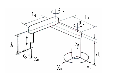
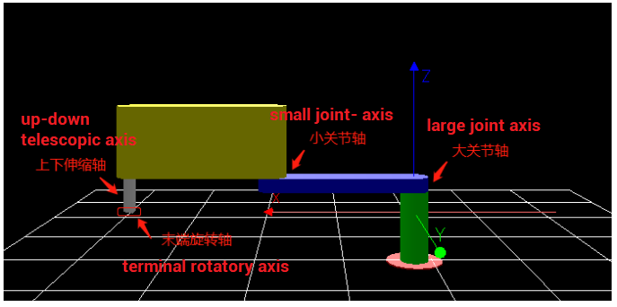
FRAME description: Frame = 1, SCARA, as shown in the figure below, the rotation axis is the joint axis, and the corresponding position at the end is the virtual position.
(3) How to use robot arm
confirm whether the motor rotation direction is correct.
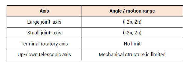
The motor direction and angle range, and the forward direction of each joint motor is shown by the arrow in the figure below.
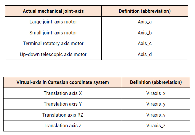
confirm that each joint axis of the robot corresponds to the axis order of the controller command parameters.
Select the axis No. of each joint axis and the corresponding virtual axis No.
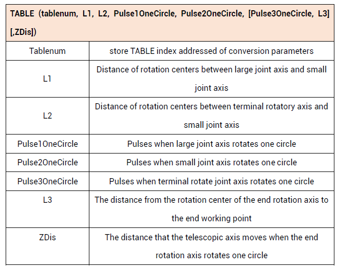
set the relevant parameters of the mechanical structure in the TABLE.
When establishing a robot connection, you need to fill in the mechanical structure parameters in the TABLE array in the following order.
set joint-axis parameters and virtual-axis parameters
The axis type and pulse equivalent of each axis must be set correctly. The length units of all virtual axes and joint axes of the robot are required to be unified, generally in mm.
The UNITS of the virtual axis has nothing to do with the actual number of sent pulses. It is used to set the motion accuracy. The number of pulses per mm of the virtual axis is generally recommended to be set as 1000, indicating that the accuracy is 3 digits after the decimal point.
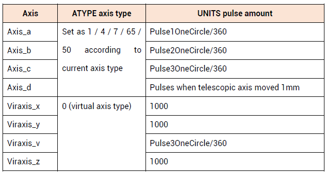
move each joint-axis to assigned origin position
When the robot arm algorithm is established, one origin position needs to be a reference, and at the same time, it is necessary to determine the direction of the motor.
It is a straight line when origin position of SCARA is the origin of two joint axes, at this time, it points to positive direction of virtual-axis axis X.
Coordinate direction: When the joint axis is at the zero point, the coordinate of the virtual axis zero point is (L1+L2,0), and there is no special requirement for the origin position of the up and down telescopic axis.
After the inverse solution connection is established, the DPOS coordinates of the virtual axis are automatically corrected to (L1+L2,0).
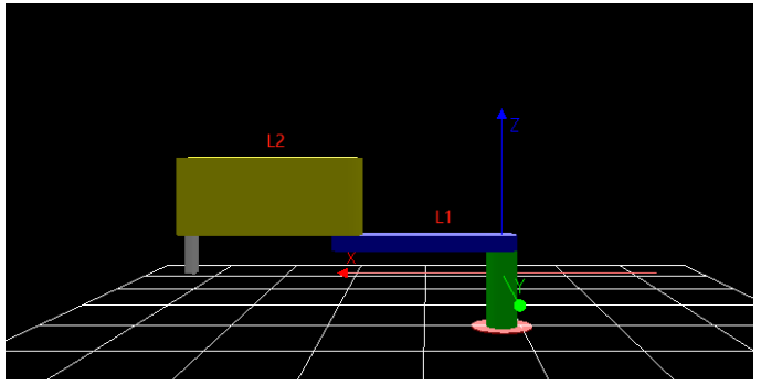
use CONNREFRAME instruction to build forward solution mode
Forward mode:
BASE(Viraxis_x, Viraxis_y, [Viraxis_v] [,Viraxis_z])
CONNREFRAME(1, tablenum, Axis_a, Axis_b[, Axis_c][, Axis_d])
WAIT LOADED
After the establishment is successful, the virtual axis MTYPE will be displayed as 34, and IDLE will be shown as 0. At this time, only the joint axis can be operated to move in the joint coordinate system, and the virtual axis will automatically calculate the position of the end working point in the Cartesian coordinate system.
operate joint-axis to adjust robot arm attitude to determine there is no interference in motion (some structures only have one attitude).
Mathematically speaking, the attitude of the robot is the solution of the same set of virtual axis values with multiple sets of joint axes. That is, when the robot moves to a certain coordinate point A in the Cartesian coordinate system, there are various motion trajectories, and these correspond to different attitudes.
The SCARA robot arm has two attitudes, the left-hand posture and the right-hand posture, and the joint axis can only be selected in the forward solution mode.
The current attitude can be checked through the "FRAME_STATUS" command.
When running in the reverse solution mode, due to the problem of the mechanical structure, there will be problems such as the inability to move to a certain position or the interference of the rigid body. At this time, it is necessary to adjust the attitude.
The attitude of the robot can only be adjusted by operating the joint axis in the forward solution mode.
use
"CONNFRAME"instruction to switch into reverse solution mode.
Inverse solution mode:
BASE(Axis_a, Axis_b [,Axis_c] [,Axis_d])
CONNFRAME(1,tablenum, Viraxis_x, Viraxis_y, [Viraxis_v] [,Viraxis_z]) WAIT LOADED
After the establishment is successful, the MTYPE of the joint axis will be displayed as 33, and the IDLE will be shown as 0. At this time, only the virtual axis can be operated to move in the Cartesian coordinate system, and the joint axis will automatically calculate how to jointly move in the joint coordinate system.
select virtual-axis, send motion instruction.
BASE(Viraxis_x, Viraxis_y[,Viraxis_v] [,Viraxis_z])
MOVE(dis_x, dis_y [,dis_v] [,dis_z])
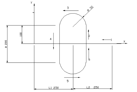
For example, the workpiece shown in the figure below is processed on an automatic welding equipment. The lengths of the two joint axes L1 and L2 of the SCARA robot arm both are 250. The trajectory to be welded is a runway type, and 1 is the initial zero point. At this time, the coordinates of the joint axes are (0,0), and the virtual axis coordinate is (500,0).
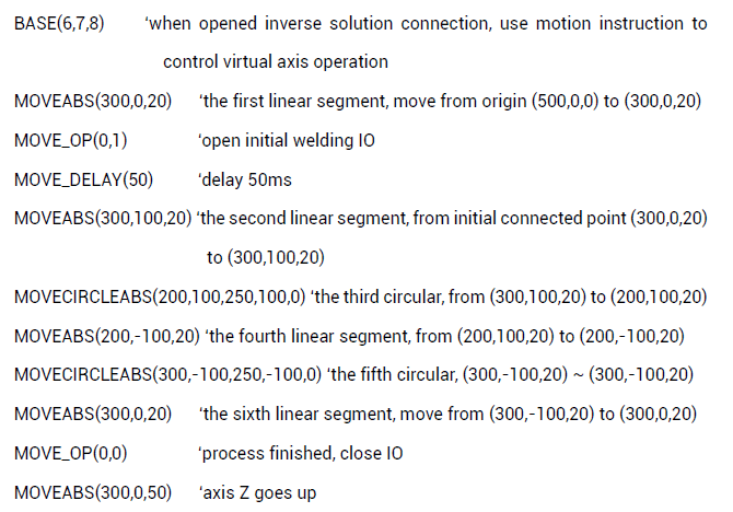
From the origin to the initial processing point, welding needs to be started in the second stage of the movement. The joint axis first returns to the initial position and then moves to the top of the workpiece while the Z-axis descends. Turn on the welding start IO and delay 50ms (because it takes a certain time for welding liquid to open, otherwise there will be missing welding at the starting point), and then run according to the track. After the runway welding is completed, the IO is turned off and the Z axis goes up.
processing codes:
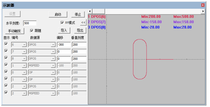
trajectory sampled by oscilloscope:
SCARA robot arm application routine
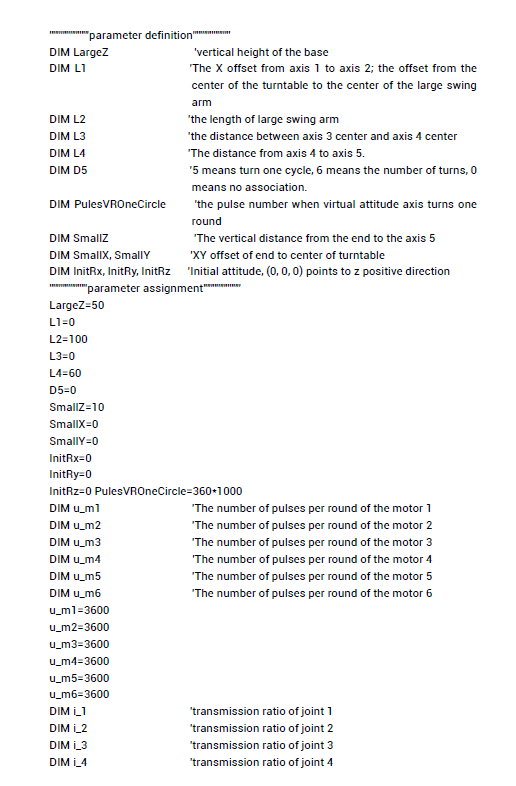
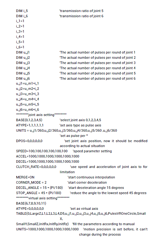
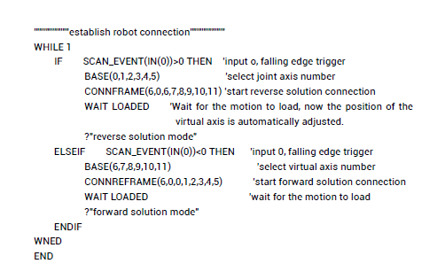
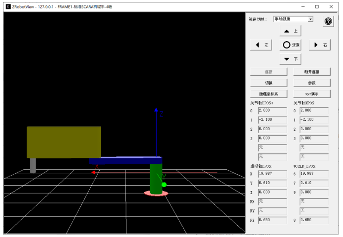
Download the program to the controller and run it. After establishing the forward solution or reverse solution connection, open ZMotion robot arm simulation software "ZRobotView", click "Connect" to pop up the window, and select the controller IP. If there is no controller, you can connect to the simulator to view the effect.
After selecting the controller IP and connecting, the following robot arm model will be displayed. At this time, you can run motion commands or manually debug to check the operation of the robot arm.
That's all, thank you for your reading -- How To Quick Start SCARA Robot Arm Application Through ZMC Motion Controller
For more information, please pay close attention to
"Support"
and
"Download"
, and there are other platforms about ZMOTION --
Youtube
&
LinkedIn
&
Twitter
&
Tiktok
&
Facebook,
including technical information (development environment, routine code), product showing, company development, etc.
Hope to meet you, talk with you and be friends with you.
Welcome!
This article is edited by ZMOTION, here, share with you, let's learn together. ZMOTION: DO THE BEST TO USE MOTION CONTROL.
Note: Copyright belongs to ZMotion Technology, if there is reproduction, please indicate article source. Thank you
.
ZMOTION Technology
has attracted experienced talents from famous companies or institutions, such as Huawei, ZET, Huazhong University of Science and Technology etc. ZMOTION insists self- innovating and collaborating with comprehensive universities, to research basic knowledge of motion control. Due to its concentration and hard work in motion control technology, ZMOTION already become one of the fastest growing industrial motion control companies in China, and is also the rare company who has managed core technologies of motion control and real time industrial control software completely.
ZMotion Technology
provides motion control card, motion controller , vision motion controller, expansion module and HMI. (
more keywords
for ZMOTION: EtherCAT motion control card, EtherCAT motion controller, motion control system, vision controller, motion control PLC, robot controller, vision positioning...)
Economical EtherCAT Motion Controller (7) --
Motion Buffer
Economical EtherCAT Motion Controller (6-2) -- Data Storgae | Register of Modbus, Table, Flash & VR
Economical EtherCAT Motion Controller (6-1) --