Here, combine high performance ZMC432 controller with hardware comparison output and precision functions that are based on FPGA to achieve
motion control + vision fly shooting, which can meet the requirement that is "high-speed & high-precision" of mechanic motion in automatic industry in a large part.
→Keywords: hardware comparison output, precision output, vision fly-shooting
“ZMOTION system introduction: motion control + vision”
1.
Motion control system
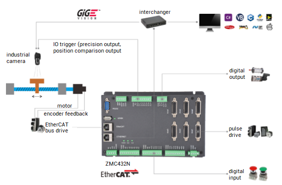
The motion control system of ZMotion Technology:
ZMC motion controller + servo drive and motor + screw rod (or driver, linear motor and grating ruler) + ...
Motion control of controller and driver is achieved through pulses sent by ZMC motion controllers or commands sent by EtherCAT bus. What's more, to do position comparison output IO signals to take photos for camera through feedback position MPOS of encoder or grating ruler.
2.
Vision system
The vision system of ZMotion Technology:
camera + shot + light source + light source control box + vision processing system + ...
There are certain requirements for camera responding time, exposure time, lens diaphragm, pixel, light source and others according to motion speed.
“Machine vision: take photos fixedly VS take photos in motion”
1.
Take photos fixedly (visual fixed shooting)
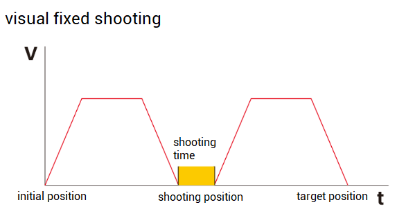
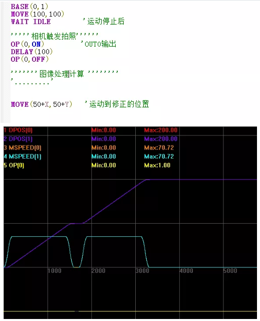
The traditional visual positioning adopts the method of fixed shooting, that is, the workpiece moves according to the assigned trajectory. When it runs to the shooting point, the speed of the motion axis will reduce to 0 and stop, then it will start to take photos, collect images, process arithmetic and correct deviation. After vision system processes finished, continue to complete the following trajectory movement, the v-t diagram is as follows.
2. Take photos in motion (fly shooting)
We could know traditional fixed shooting is low efficiency, therefore, another method,
fly shooting is used to achieve vision shooting function increasingly.
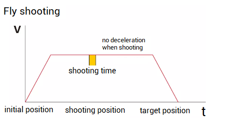
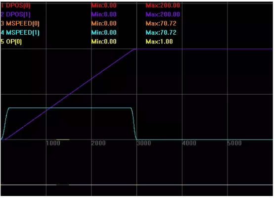
Fly shooting means motion axes don't stop at the shooting position in assigned motion trajectory, then it can take photos instantly.
In the whole process, moving institute does not stop,
which means running time can be reduced and efficiency can be met, at the same time, the running accuracy can be promised definitely.
Ø
Precision is promised, but no deceleration:
Ø
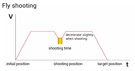
Precision is not enough, and slow down lightly, run in several parts, but speed won't be 0:
“Achievement methods of controller visual fixed shooting and fly shooting”
1. Visual fixed shooting
ü
It is achieved through normally IO output.
In machine vision system, fixed shooting adds the times of axis' on-off in motion, which means the Cycle time of whole process is increased correspondingly, then it causes low efficiency and vibration of machine because of frequent switch on and off in motion, even it will influence manufacturing precision in some high-speed and high-precision occasions.
2. Fly shooting
ü
It is achieved through one controller that supports hardware comparison output or precision output function.
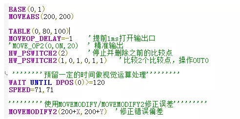
When run at assigned shooting position, motion axes won't stop, then use motion controller's precision output function or hardware comparison output function to finish taking photos in motion instantly.
In motion process, mechanic coordinates offset can be calculated according to product pixel position changes captured by visual fly shooting, then send the offset to motion controller for correction in time, this is the full fly-shooting function.
What's the guarantee for precision in whole fly shooting process?
-- real-time when trigger IO shooting, image acquisition and processing speed.
Whole precision of Zmotion motion controller's hardware comparison output based on FPGA, from driver to shooting position, then finish trigger at camera position can be controlled in 1 pulse (the minimal error) of pulse output mode and within 1us (the minimal error) of bus control mode.
When motor is with encoder or grating ruler feedback, hardware comparison output function automatically uses feedback position MPOS to trigger. However, when there is no with feedback, it uses send position DPOS automatically. Different drives bring different effects. Also, MOVE_DELAY can be used to adjust accurate time of IO output.
Multiple achievements and adjustments extremely ensure precision of visual fly shooting for controller in high-speed and high-precision occasions.
“ Related instructions of hardware position comparison output”
1.
Basic programming:
1)
HW_PSWITCH -- hardware position comparison output
--HW_PSWITCH(mode, direction, reserve, tablestart, tableend)--
Ø
Mode: 1 -- open comparer, 2 -- stop and delete comparison points that are not completed.
Ø
Direction: 0 -- negative of coordinate, 1 -- positive of coordinate, 2 -- no direction judgement
Ø
Reserve: reserved
Ø
Tablestart: TABLE No. of the first comparison point
Ø
Tableend: TABLE No. of the last comparison point
2)
HW_PSWITCH2 -- bus hardware position comparison output
--HW_PSWITCH2(1,opnum,opstate,tablestart,tableend[,direction])—
Ø
Mode: 1 -- open comparer
Ø
Opnum: relative output
Ø Tablestart: TABLE No. of the first comparison point
Ø Tableend: TABLE No. of the last comparison point
Ø Direction: the first point to judge direction: 0 -- negative of coordinate, 1 -- positive of coordinate, 2 -- not use direction
3)
MOVE_OP -- precision output
--grammar 1: MOVE_OP ([ionum],value)--
Ø
ionum: output No., 0-, if there is no this parameter, output 0-31
Ø
value: output status, when multiple output ports are operated, then indicate the status of multiple ports by bit.
--grammar2: MOVE_OP (ionum1, ionum2,value[,mask])—
Ø
ionum1: the first output channel to be operated
Ø
ionum2: the last output channel to be operated
Ø
value: output status, when multiple output ports are operated, then indicate the status of multiple ports by bit.
Ø
mask: set the value as bit, assign which IOs to be operated, if it is not filled, all channels are operated.
4)
MOVEOP_DELAY -- buffer output delay
--MOVEOP_DELAY=timems—
Ø
timems: milliseconds
Ø
This is set in BASE main axis, when MOVE_OP precision function is used, it can advance or delay the time of actual triggering OP.
2.
Instruction function relates to function libaray of PC upper computer program (C
、
C++
、
C#
、
Delphi
、
VB
、
.Net
、
LabVIEW
、
Python
、
matlab)
Ø
ZAux_Direct_HwPswitch
Ø
ZAux_Direct_HwPswitch2
Ø
ZAux_Direct_MoveOp
"Conclusion of visual fixed shooting VS fly shooting"
Machine vision technology is an effective way to achieve precise control, intelligence, automation and modernization of equipment and one of the basic technologies for computer integrated manufacturing. Machine vision can not only replace the detection of the artificial naked eye, but also identify the detection range that cannot be seen by the artificial naked eye. With the increasing demand for production efficiency and capacity, the development of high-speed and high-precision + machine vision is particularly important in the field of automation.
A variety of motion controllers/motion control cards in ZMotion can be matched with different PC hardware platforms according to system requirements,
to achieve a visual flying accuracy of up to 10um at a running speed of 2m/s, and reduce the running speed to achieve repeatability within 1um. This solution is widely used in more and more industries (such as 3C, electronic semiconductors, packaging, robot applications, etc.).


