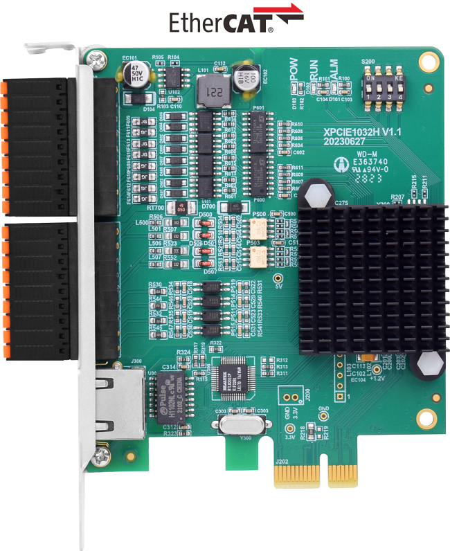
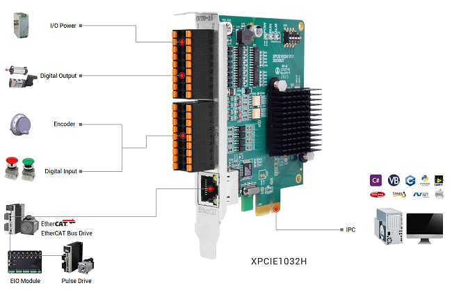
--XPCIE1032H Hardware Info--
Axis Control: 4-64 axes
IO control: high-speed digital IO for latch, PWM, PSO, encoder IN.
Interface: EtherCAT (motion control & IO expansion)
Development: PC programming languages -- C#, C++, Labview, Python, etc.
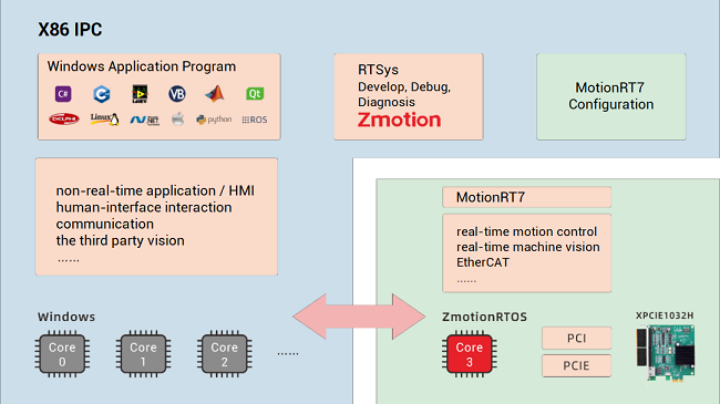
--XPCIE1032H Software “MotionRT7”--
High-speed kernel interaction brings faster command interaction: one single command & multi-command interaction time (once) can reach about 3-5us (below shows the test result).

--XPCIE1032H Card & MotionRT7 Soft Kernel--
P 1D/2D/3D PSO (high-speed hardware position comparison output): suit to vision fly-shooting, precise dispensing, laser energy control, etc.
P EtherCAT & pulse axes: hybrid linkage, and hybrid interpolation.
P in PC Windows development, it can achieve real-time, and the instruction interaction speed is faster 10 times than traditional PCI / PCIe.
[ XPCIE1032H IO Configurations Introduction ]
(1) XPCIE1032H IO Introduction
--XPCIE1032H IO Interface Specification--
Item | Specification | Description |
Internal IO | 16+16 | 16 inputs, 16 outputs (with overcurrent protection) |
Max extended IO | 512 inputs, 512 outputs | Extended IO numbers by EtherCAT expansion modules. |
High-speed input | 8 | IN0-7, 8 are high-speed inputs |
High-speed output | 16 | OUT0-15, 16 are high-speed outputs |
Latch input | 4 | 4 can be configured as latch input, IN0-3 |
Single-ended encoder | 2 | Input is reused, IN0-2, IN4-6 |
PWM output | 4 | 4 can be configured as PWM, OUT0-3 |
Hardware comparison output | 16 | 16 outputs can be configured as hardware comparison output (PSO), and precision output can be compatible, OUT0-15.
|
Single-ended pulse output | 4 | Output is reused, OUT8-15 |
IO power input | DC24V | 24 DC input, IO needs to be supplied by external power separately. |
--XPCIE1032H IO Terminals--

For its IO terminal definitions, please refer toXPCIE1032H EtherCAT Motion Control Card User Manual.
--Notes--
Ø Only 24V encoders can be used. The maximum pulse frequency of encoder 0 and encoder 1 is 500kHz, which can be connected to high-speed encoders, the others are common inputs, the maximum pulse frequency is 10kHz, and it can only be connected to low-speed encoders such as handwheels.
Ø The No. after inputting pulse output and encoder input is default axis No., and it can be switched into ordinary IO through ATYPE command (ATYPE = 0: ordinary IO, ATYPE = 1: pulse output, ATYPE = 3: encoder input, ATYPE = 4: pulse output + encoder input)
(2) How to Configure IN as Encoder
Axis Type ATYPE:
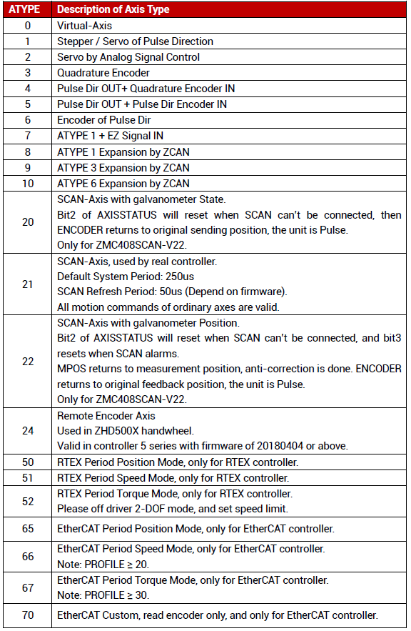
XPCIE1032H has 2 single-ended encoder inputs of 24V.
Here, use IN4-6 to connect to the encoder.
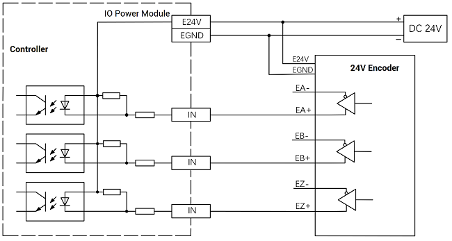
A. Controller IN & Encoder Wiring
Please wire them at first according to below graphic.
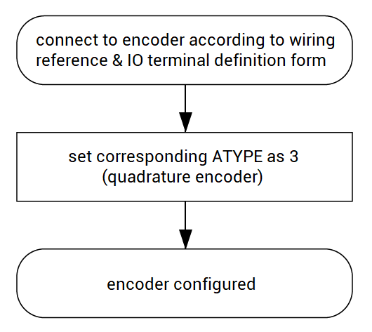
IN 4 = EA1, IN5 = EB1, IN6 = EZ1, then corresponding encoder axis No. is 1 after wired.
Then, set ATYPE (axis type) of axis 1 as 3 in C#, 3 means quadrature encoder.
After that, IN can be used ass encoder input signals.
a. Read ATYPE by axis No.
private void C_Move_Axis_TextChanged(object sender, EventArgs e)
{
if (g_handle == (IntPtr)0)
{
return;
}
int ret = 0;
int m_atype = 0;
m_axisnum = Convert.ToInt32(C_Move_Axis.Text);
ret += zmcaux.ZAux_Direct_GetAtype(g_handle, m_axisnum, ref m_atype);
if (ret == 0)
{
C_AxisType.Text = m_atype.ToString();
}
}
b. Set ATYPE by axis No.
private void C_Move_Axis_TextChanged(object sender, EventArgs e)
{
if (g_handle == (IntPtr)0)
{
return;
}
int ret = 0;
int m_atype1 = 0;
m_atype1 = Convert.ToInt32(C_AxisType1.Text);
m_axisnum = Convert.ToInt32(C_Move_Axis.Text);
zmcaux.ZAux_Direct_SetAtype(g_handle, m_axisnum, m_atype1);
}
(3) How to Configure OUT as Pulse
XPCIE1032H has 4 single-ended pulse outputs.
Here, use OUT8 and OUT9 to connect to the drive.
A. Controller OUT & Drive Wiring
Please wire them at first according to below graphic.
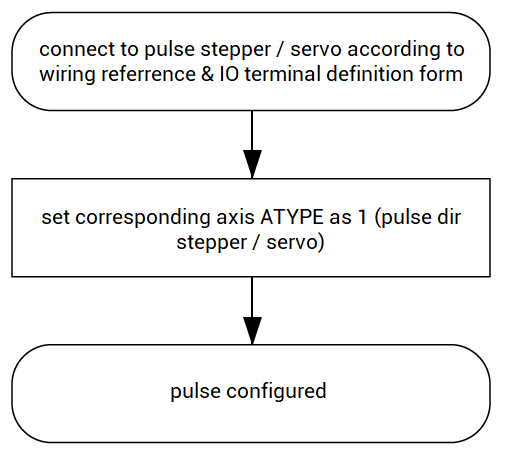
OUT8 = DIR3, OUT9 = PUL3, so corresponding pulse drive axis No. is 3.
Then, configure ATYPE of axis 3 as 1 in C#. 1 means the type is pulse directional stepper / servo.
For the drive, it can be connected to E24V / E5V.
a. Read ATYPE by axis No.
private void C_Move_Axis_TextChanged(object sender, EventArgs e)
{
if (g_handle == (IntPtr)0)
{
return;
}
int ret = 0;
int m_atype = 0;
m_axisnum = Convert.ToInt32(C_Move_Axis.Text);
ret += zmcaux.ZAux_Direct_GetAtype(g_handle, m_axisnum, ref m_atype);
if (ret == 0)
{
C_AxisType.Text = m_atype.ToString();
}
}
b. Set ATYPE by axis No.
private void button1_Click (object sender, EventArgs e)
{
if (g_handle == (IntPtr)0)
{
return;
}
int ret = 0;
int m_atype1 = 0;
m_atype1 = Convert.ToInt32(C_AxisType1.Text);
m_axisnum = Convert.ToInt32(C_Move_Axis.Text);
zmcaux.ZAux_Direct_SetAtype(g_handle, m_axisnum, m_atype1);
}
[ XPCIE1032H Extended IO (EIO16084) Configurations Introduction ]
(1) What is EIO16084
EIO16084 is one EtherCAT remote IO module developed Zmotion, which is mainly matched with Zmotion EtherCAT motion controllers to extend more IOs and pulse axes.
One EIO16084 can extend 16 digital inputs, 8 digital outputs, and 4 pulse axes. For one motion controller, multiple EIO16084 can be used at the same time. Except that, EIO24088 (expand 24 IN, 8 OUT, 8 pulse axes), ZMIO series are valid.
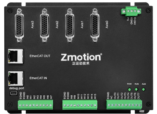
How many IOs and axes the controller allows, please check Controller State in RTSys.
RTSys is Zmotion own free IDE software, it can develop, debug, and diagnose programs for Zmotion motion controllers.
(2) EIO16084 & XPCIE1032H Wiring
EIO16084 module uses single-power, and the main power is 24V DC, which can supply power for IO.
Below shows the wiring of XPCIE1032H motion control card and EIO16084 IO module.
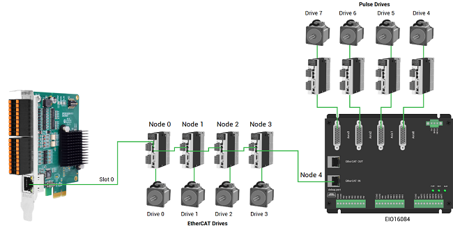
After wiring, no need to develop EIO16084. You only need to manually configure motion controller unique IO address through NODE_IO command (details can be known from Basic Programming Manual).
Then, EIO16084 resources can be accessed by IO No., used for motion controller.
Please note, EtherCAT IN connects to former module, EtherCAT OUT connects to next module.
It is controller bus interface No., and the slot No. of the EtherCAT bus is 0.
The device number refers to the No. of all devices connected to a slot. It starts from 0 and is automatically numbered according to the connection sequence of the devices on the bus. You can view the total number of devices connected to the bus through the NODE_COUNT(slot) command.
The controller will automatically identify the drive on the slot, and the number starts from 0, and the number is automatically numbered according to the connection sequence of the drive on the bus.
The drive number is different from the device number. Only the drive device number on the slot is assigned, and other devices are ignored. The drive number will be used when mapping the axis number.
(3) EIO16084 Interfaces
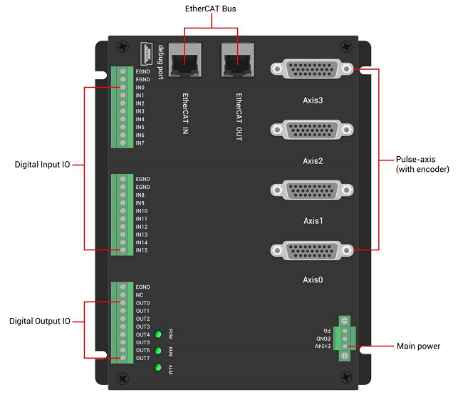
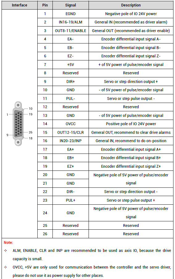
It can be known EIO16084 supports 4 local differential pulse axes, and each interface is standard DB26 female.
And they can be configured as differential pulse output and differential encoder input.
(4) Configure as Encoder & Pulse
A. Wiring Reference
*pulse*
The wiring example of Panasonic A5/A6 servo drive:
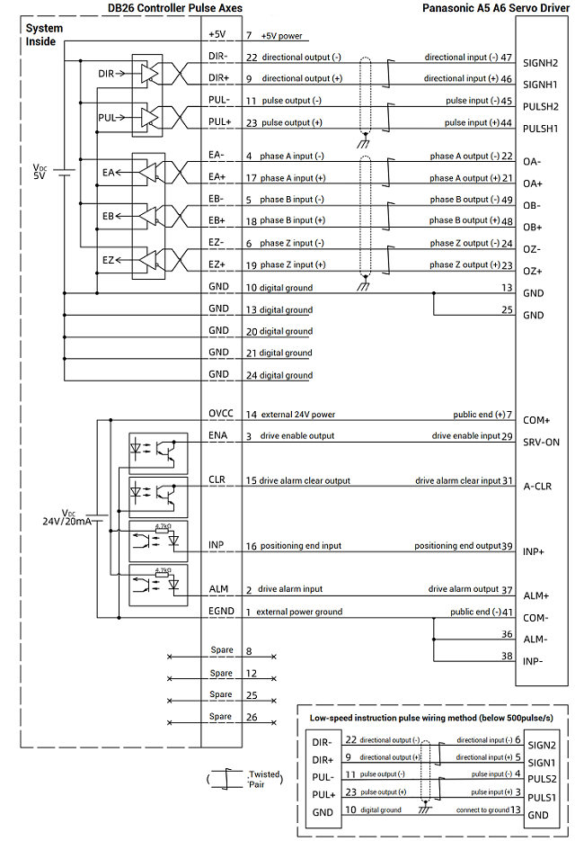
After wiring, write data dictionary to configure EtherCAT axis’ real axis type in C#. The real ATYPE is set by data dictionary 6011h.
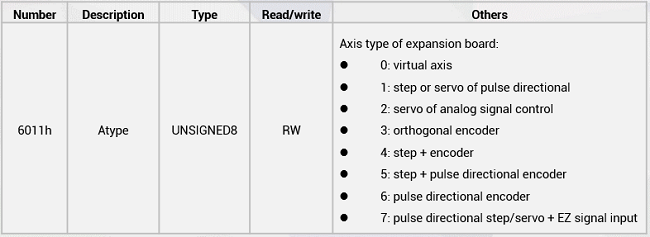
In C#, write “ ZAux_BusCmd_SDOWrite (handle, slot, Node, data dictionary No., data dictionary Sub No., data type, data val ue)”.
Set it as the order of axis No., the first drive should be 6011h+0*800h, the second one should be 6011h+1*800h……
*encoder & pulse*
SDO Writing by node and slot.
private void C_Sdo_Write_Click(object sender, EventArgs e)
{
    if (g_handle == (IntPtr)0)
    {
        MessageBox.Show("No Controller Connected!", "Note");
        return;
    }
    int ret = 0;
    uint m_sdo_slot1 = Convert.ToUInt32(C_SdoSlot0.Text);
    uint m_sdo_node1 = Convert.ToUInt32(C_SdoNode0.Text);
    uint m_sdo_index1 = Convert.ToUInt32(C_SdoReg0.Text);
    uint m_sdo_sub1 = Convert.ToUInt32(C_SdoIsub0.Text);
    uint m_sdo_type1 = Convert.ToUInt32(C_SdoType0.SelectedIndex.ToString()) + 1;
    int m_sdo_data1 = Convert.ToInt32(C_Sdodata0.Text);
    if (Bus_type == 0)
    {
        ret = zmcaux.ZAux_BusCmd_SDOWrite(g_handle, m_sdo_slot1, m_sdo_node1, m_sdo_index1, m_sdo_sub1, m_sdo_type1, m_sdo_data1);
        if (ret != 0)
        {
            MessageBox.Show("Write Failed");
            return;
        }
    }
    else
    {
        MessageBox.Show("Non-ETHERCAT Module");
        return;
    }
}
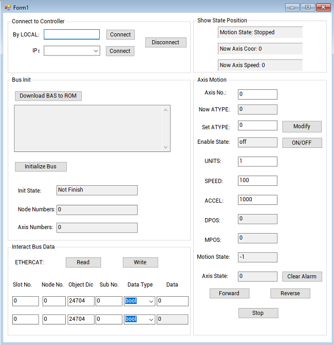
The routine will be described in next article “(5-2) | C# IO Configurations Routine”.


